Bracket Bot
The longest robotics project I've ever worked on
One of my favourite hackers, George Hotz, founder of comma.ai, recently mocked Tesla by coming out with the "comma body" seen below. Comma.ai is a company that like Tesla, is aiming to solve self driving - though their approach is much different. While Tesla was collecting data from their fleet of cars, George was crowdsourcing driving data through an app called chffr from a community of hackers. While Tesla was designing custom silicon for self driving computation, George and the comma team were modifying android phones to tap into the CAN system of steer by wire cars and perform simple ADAS. At one point comma had the highest ADAS rating of any automaker with the comma two - including Tesla autopilot. And finally, when Tesla revealed that it wanted to make a humanoid robot in August of 2021, George announced the comma body, a hoverboard with a piece of extrusion and a comma three on top. What a mockery.

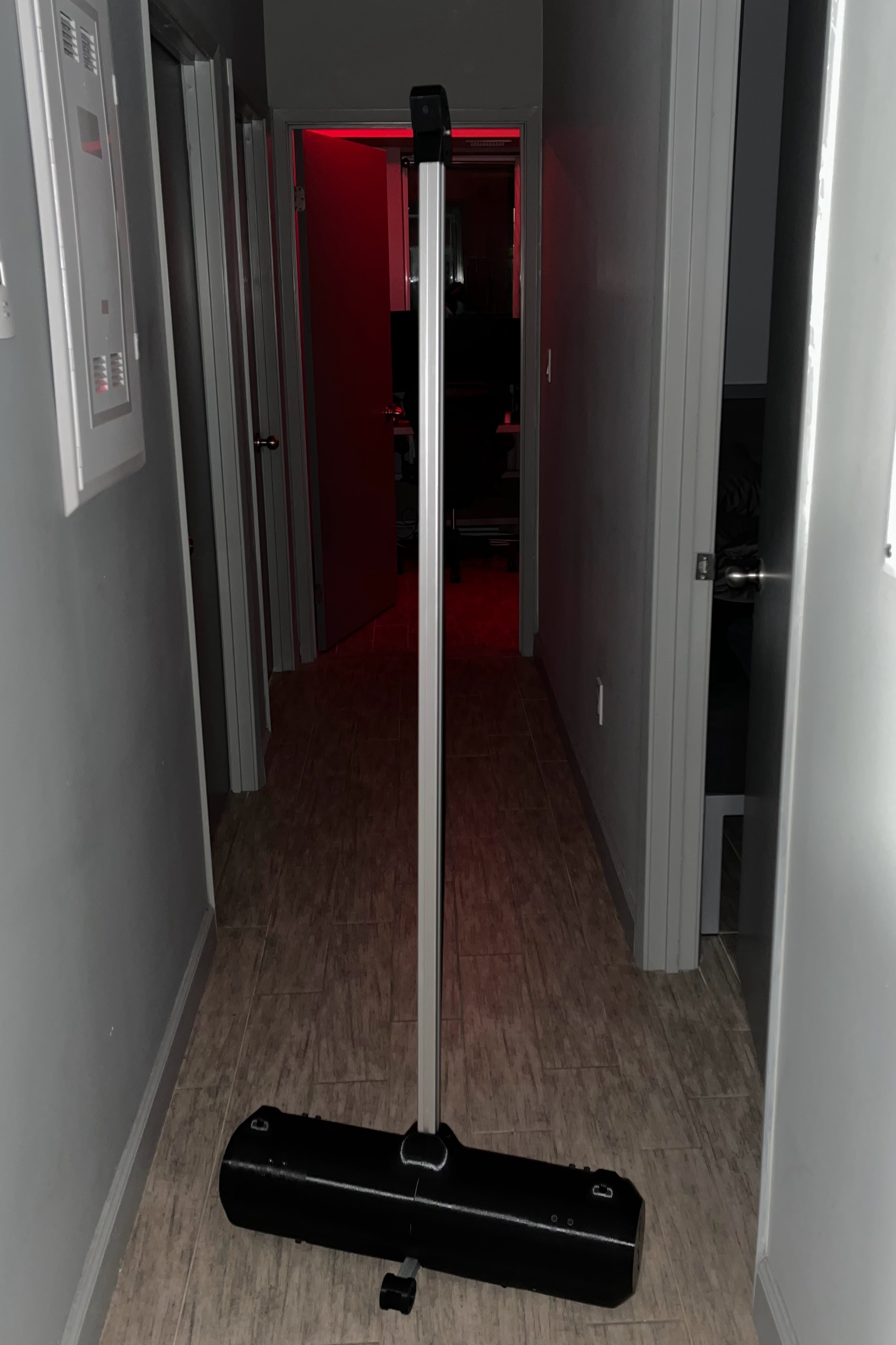
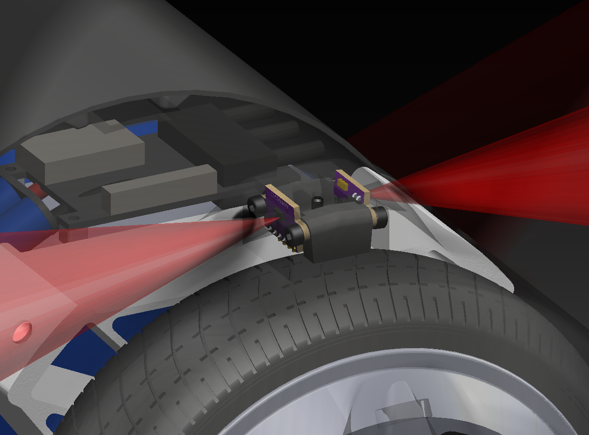
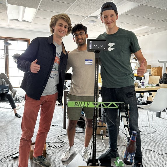
Times are changing, meet Bracket Bot. Inspired by the simple form factor of the comma body, bracket bot is built very similarly. The segway form factor allows for easy controls and a cheap mechanical structure. Bracket bot uses 2 brushless hoverboard wheels to drive, much like the comma body, but paired with high resolution encoders and state of the art motor controllers. The structure is simply a piece of 4040 extrusion, a bracket, and another vertical piece of 4040 for the "mast". Inside the enclosure is a custom built battery, a Jetson Nano, and 4 long distance time-of-flight sensors. Atop the mast standing at 5'8 is a wide angle camera, in conjunction with an additional time-of-flight sensor.
This projects idea came from my good friend Brian Machado. Ethan Childerhose of bigcrete.engineering and Ivan Yevenko helped get the first few prototypes running, including the one talked about in this blog. Ethan designed a high power buck converter for the power hungry Jetson Nano, wrote a custom software SPI library, and worked with me on the firmware development. Ivan wrestled with ORB-SLAM and added functionality for local and global floor detection which helped with accurate homography, he also critiqued my crazy perception ideas. We aimed to have the project done within two weeks, but after running into significant motor controller problems and realizing the software was harder than anticipated, it lasted months and still never got completed. Typical.
Although I am sad this initial version failed, it turned into something beautiful in the end
People love to hate on the Tesla Bot form factor, I for one think that it makes sense for a lot of things. The one thing I don't think it makes sense for is manufacturing, which confuses me since it's supposed to be the first use case of the Tesla Bot. The things that are hard for machines to do are not hard because of the form factor, they are often hard because they need finesse. A fine degree of sensor fusion and processing. For example it's hard for robots to route cable harnesses through cars, yet trivial for humans. This is because humans have great force feedback, an understanding of cable physics, great 3D perception of where the cable is, but not because of the human form factor. It is often this case across the assembly line, trust me - i've walked it. Where the form factor really makes sense is in spaces designed for humans that can't change as easily as an assembly line. Anytime a door needs to be opened, or stairs need to be climbed, or even getting into a car (just watch the 2015 DARPA robotics challenge) you'll want a humanoid form factor.
To be able to interact with human spaces, you need to accurately reflect the human body with around 30-40 DOF. But the goal of Bracket Bot was just to have a presence in public spaces, specifically in our buildings engineering build E5. This meant it had to be able to ride elevators, go over small bumps, and not block hallways or tight spaces. To meet these requirements, we made the robot roughly the size of an average human. It uses 8" wheels to traverse over large bumps and thresholds. Although not as close to a human as the Tesla Bot it's surely close for 20X less degrees of freedom.
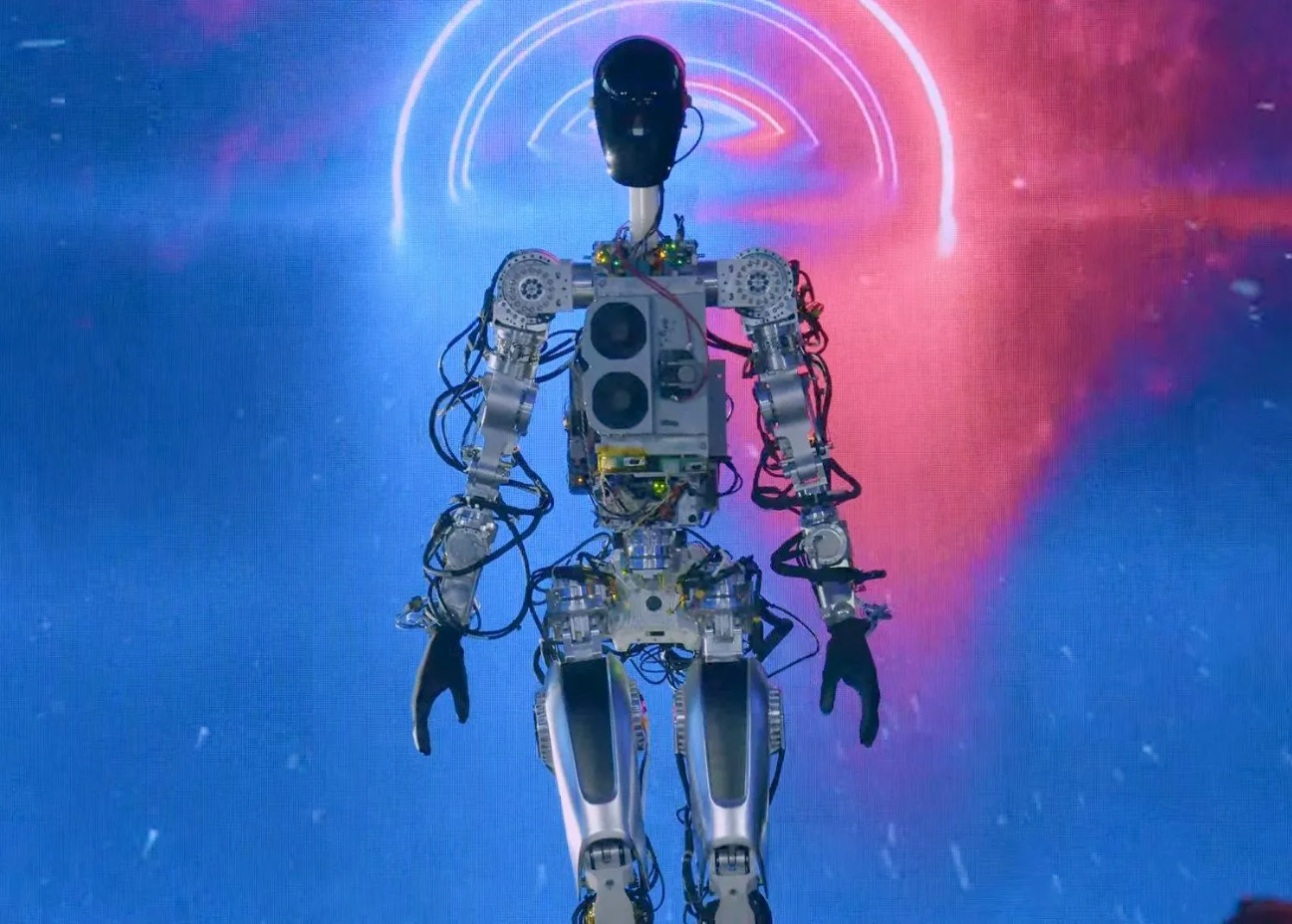
So this is why we picked the form factor, same stance and height as the average human. The segway allows for high speeds and great maneuverability in a small package. Similar eye placement to that of humans lets us get a wide angle view from high up, and a high mass moment of inertia for the segway.
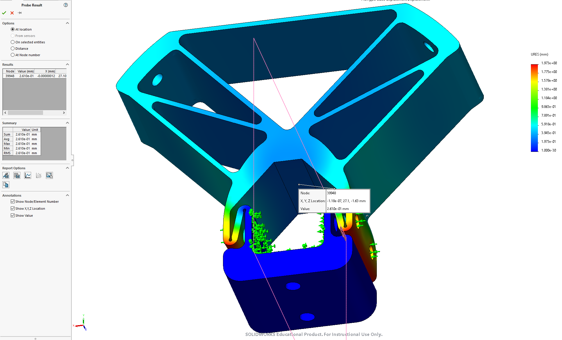
I knew what we had to work with before the project started. I pooled together components with my roommates and some other friends to get this built as soon as possible. We gathered 3 Prusa's in our apartment and started printing stuff 24/7, iterating fast with the initial 2 week goal in mind. We had a ton of 8" hoverboard wheels from broken hoverboards, as well as the 18650s that came with them. So I knew we could work with those. They have a D shaft to interface with so I designed a 3D printed flexure to clamp onto it (see below). Although using plastic was suboptimal for a part with such high contact stresses, it was what we had to work with. For the chassis I used a bunch of 4040 with 3D printed brackets (hence the name). Similar to the comma body I added a kickstand, which would catch the robot if it fell or died instead of face planting. On the ends of the kickstand were print-in-place wheels for prototyping and testing.

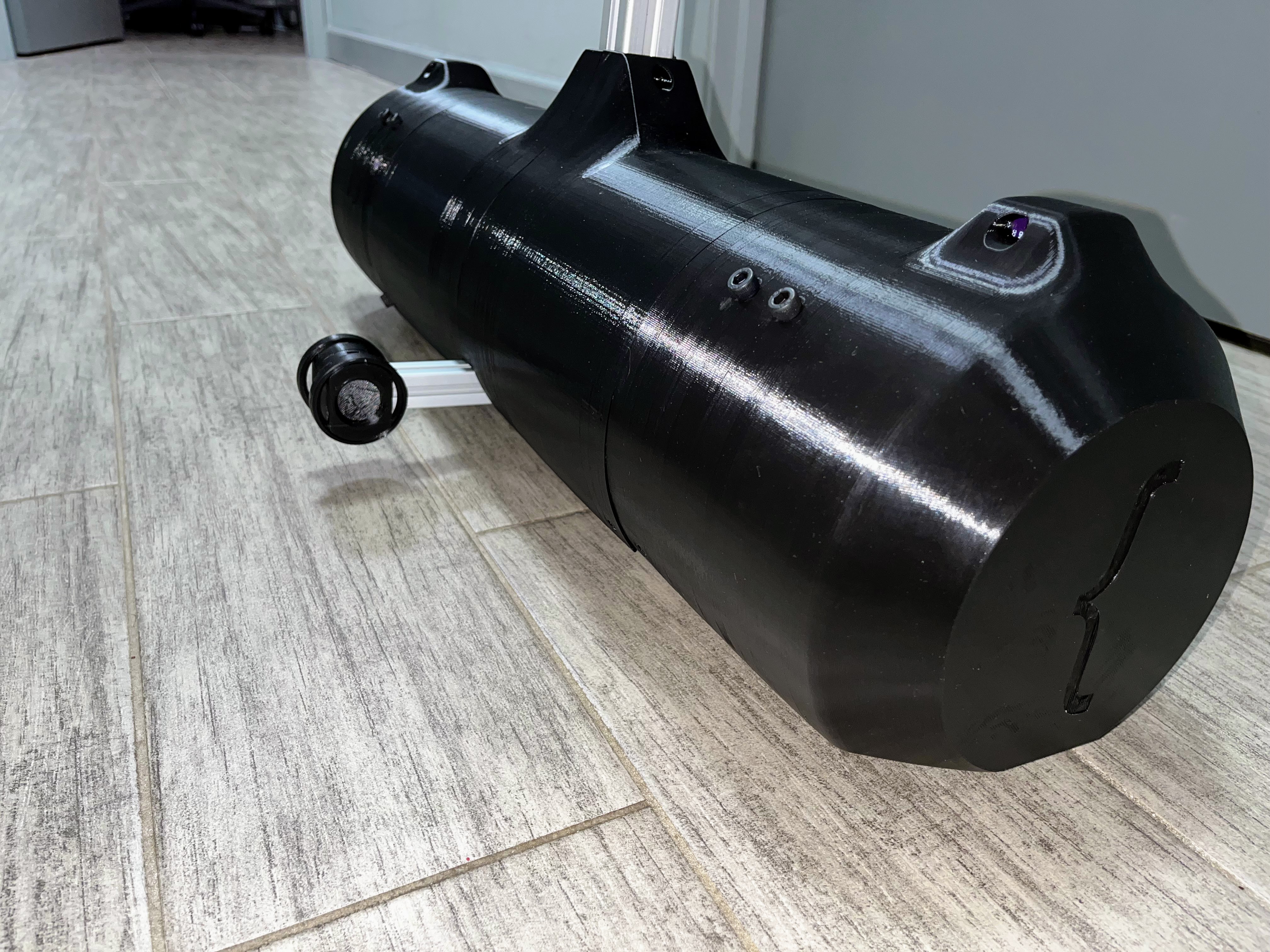
The enclosure is pretty clever, it's 4 pieces with interlocking features that keep the outer surfaces aligned. FDM prints have a pretty characteristic texture and along with the gloss, it makes it very obvious when they aren't aligned. Each piece is supported by spokes (shown below in white) which keeps the enclosure strong enough to support the weight of the robot in any crash orientation (with the kickstand removed). To align each piece, 2 dovetails that purposefully over constrain the assembly are attached to mating pieces. They flex the parts to be concentric and reduce warpage. The end pieces are also used to mount the wheel encoder and Time-of-Flight sensor.

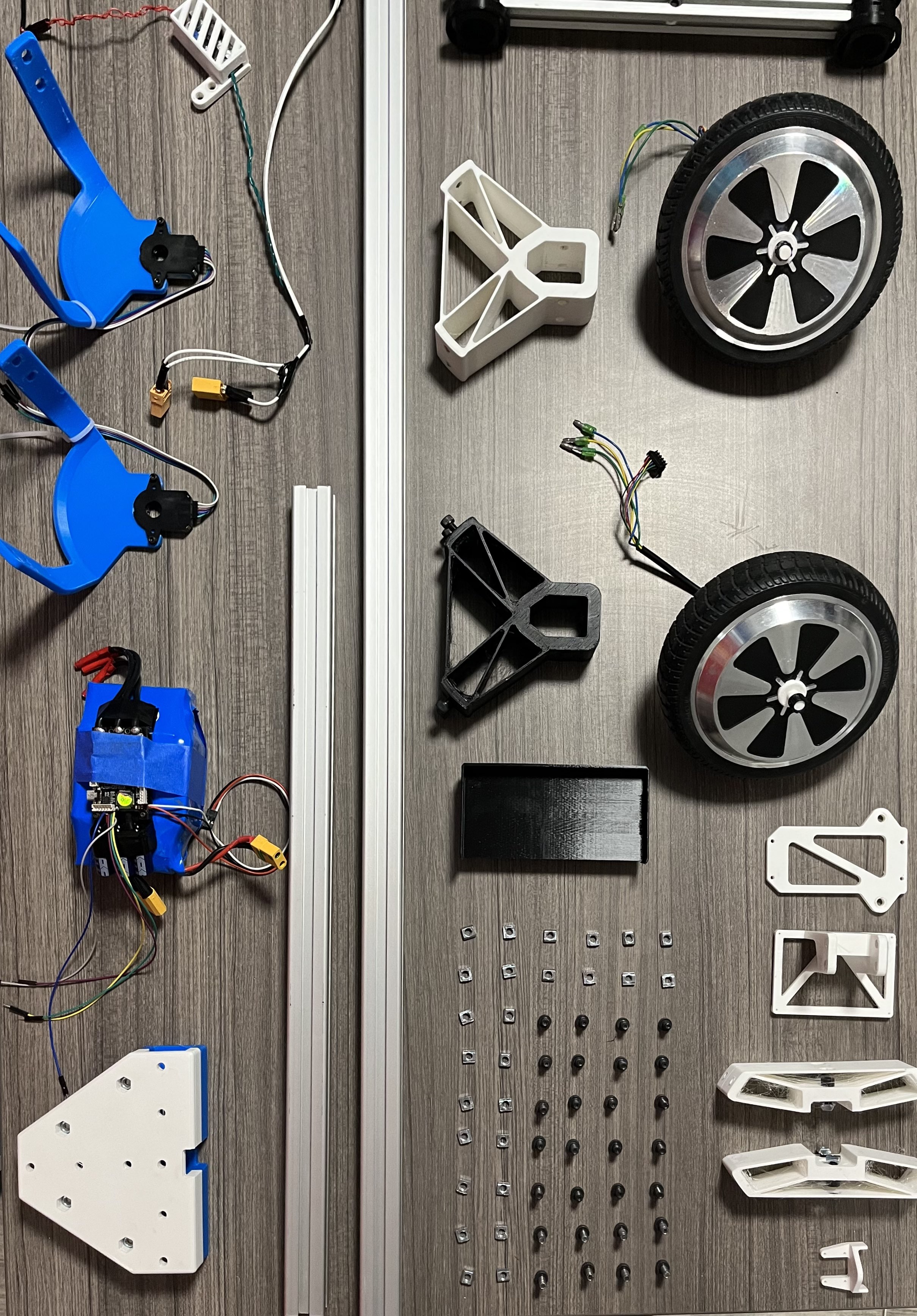
Below you can see how simple the core assembly is. Many of these parts ended up getting combined into the enclosure, making the BOM even smaller.
I wish the mechanical aspect of this project was more complicated, I wanted to add a simple arm. Or something challenging. The hardest part was the enclosure fitment and panel gap, which is fantastic because I work at Tesla. I eventually ran out of things to do and started the electrical and even software myself (which wasn't supposed to be my part of the project for a good reason).
Bow down to your evil robot overlord.

Let me preempt this - the wire routing is not my best work. The electrical layout is shown below, showing most of the buses and power connections. I learned about how big of a problem wire routing is, even with 2 motors and motor controllers, I can't imagine scaling up to Tesla Bot level. One of the big things I realized is how important it is to reduce wires per actuator. We were forced to use SPI because of our motor controller selection, which required 5 wires per controller (2 chip selects). Tesla Bot uses CAN as far as I can tell, which means 2.5X less points of failure, and 2.5X less wire to route per actuator.

Let's start with power distribution. Power directly from the battery gets distributed to each motor controller. The Jetson is power hungry, consuming 25W at max computation (which we will basically always be at) at an annoyingly low voltage of 5V. With no good high power 5V bucks on the market, Ethan decided to design and build his own using a 45V 5A DC-DC converter from TI.
Modern day FOC brushless motor control is kind of a weird duopoly. You have two good hobby options, VESC (and all of its copies) or O-Drive. Both of these options have a ton of features in terms of position, velocity, torque control and different sensored and sensorless techniques. Both of them are also pretty pricey, and we weren't able to get a sponsorship from either company. We started out with some spare VESCs we had lying around, but one of them was fried, forcing us to go another route. There is a third option that some hobbyists use, but it comes with unique challenges. Trinamic Motion Control, a German company making custom silicon motor controllers. Bought by Maxim Integrated (who is in turn owned by Analog Devices) it sounds as messy as it is. Although they very generously offered to sponsor our project by sending us two 4671+6100 breakout boards, they were a huge pain to work with. There was no available library for the Jetson so we were forced to write our own by writing bytes directly to memory addresses. On top of this, the Jetson only supports 2 hardware SPI chip selects, so Ethan had to write a custom software SPI library to use 4 devices on the line. Luckily, Trinamic provides an IDE that allows you to tune your control values and motor parameters. Unluckily, it is the worst software I have ever used. It is incredibly unstable, most versions didn't even work at all. Enjoy some actual screenshots below.


Once we finally got a usable tune on the motors, it was time to write the control code which I'll go into in the software section. Trinamic only lets you command a velocity in integers, meaning no less than 1rpm! That means that the control loop couldn't react until it commanded a velocity that rounded up to 1, which drastically hurt the stability. The controllers would also randomly set 363rpm to the velocity registers non-deterministically when we set the drive mode to stop. We still don't know why this was the case, and this was the main bug holding us back from completing the project.
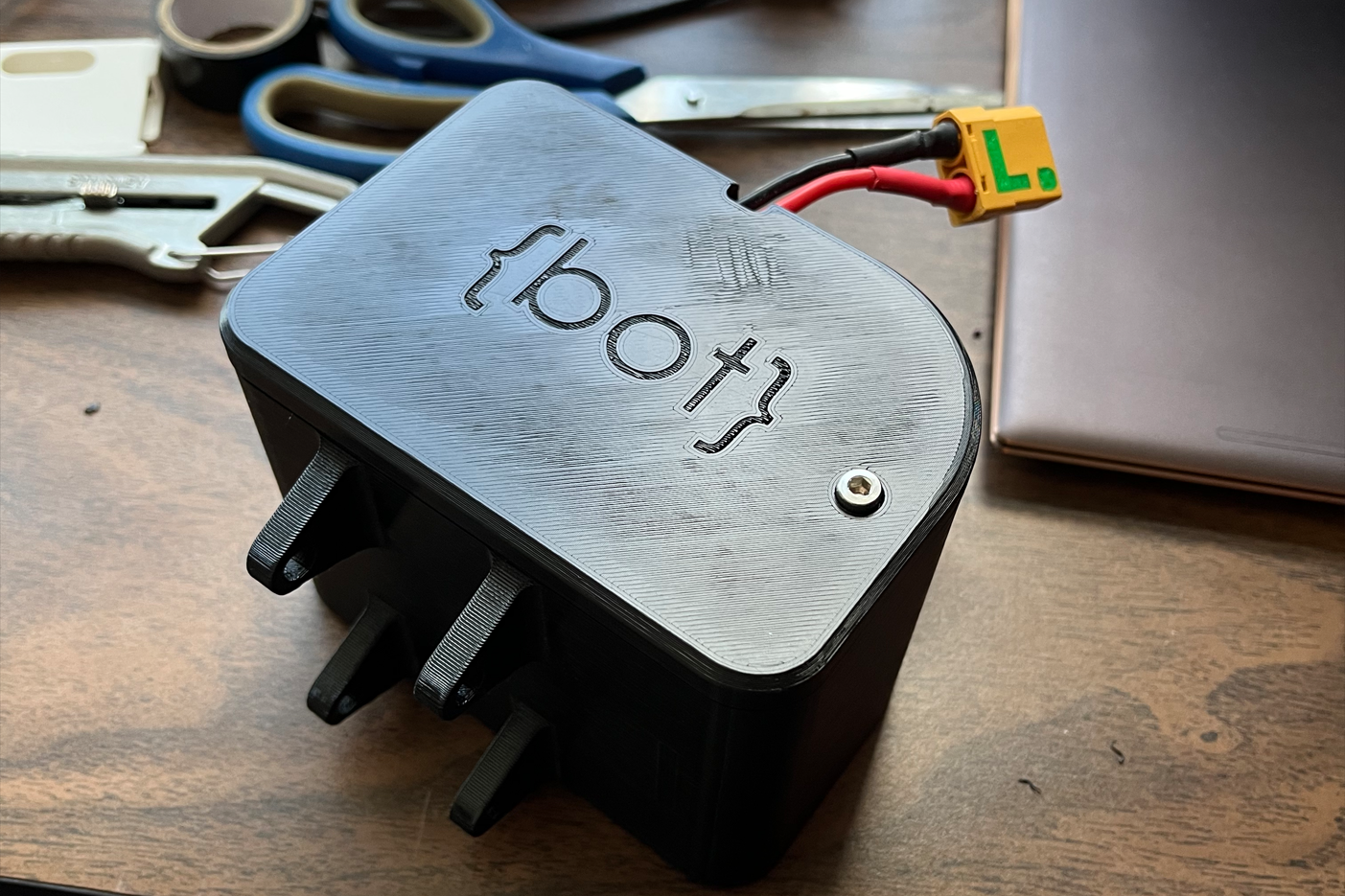
Next I'll talk about the battery. It was a pretty simple problem, we scavenged 18650 cells from hoverboards and spot welded them together with the generous help of Waterloo's Solar Car team, Midnight Sun. We used the same voltage as a hoverboard (10S) and as many cells as we could in parallel (2P). Some rough napkin math shows it should last around 30 minutes of casual driving. I built up a nice 4040 friendly enclosure with a BMS included, seen below.
Let's talk about our sensor suite. I gained a lot of insight into robotics perception through my internship at Matician, working with some of the most talented CV engineers in robotics. I've written about this before on my blog - but I think courses should strive to be more like this one. The rundown of the syllabus was teams of 3 - 6 will compete to complete a robotics challenge that will be announced in the second week. Your mark of the course is highly dependent on your competition score, which is calculated as:


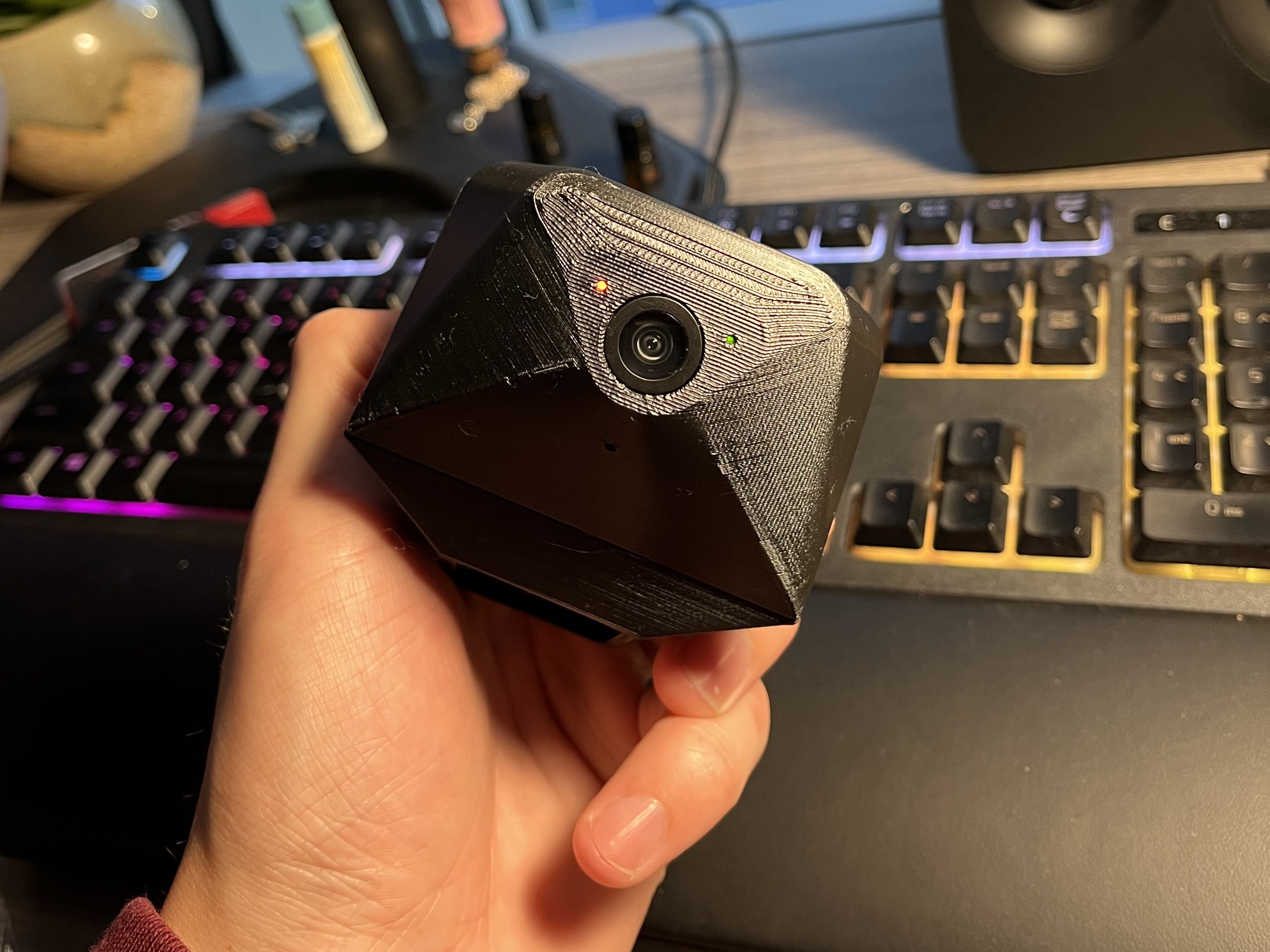
We started with a simple USB webcam, but it had horrible stability and white balance issues. Luckily the Jetson came with 2 CSI connectors for a MIPI interface, so we used a PiCam V2 which to my surprise was much better than the webcam. I liked the original webcam enclosure much better, I think the PiCam enclosure was really ugly. The two revisions are shown below.

As for the compute, our options were super limited here so this was brief. We knew we wanted something with CUDA cores for accelerating our ML models, but not much was available. Everything was sold out, and reselling for much more online. We wanted a Jetson TX2 but ended up with a Jetson Nano that a friend had lying around. This was okay, but ended up being super slow running our semantic segmentation model (only running once per 4 seconds) so we debated sending the video feed to one of our PCs with a beefier graphics card and running models off device, but this never happened. We probably could have optimized the model too, if we did some performance analysis.
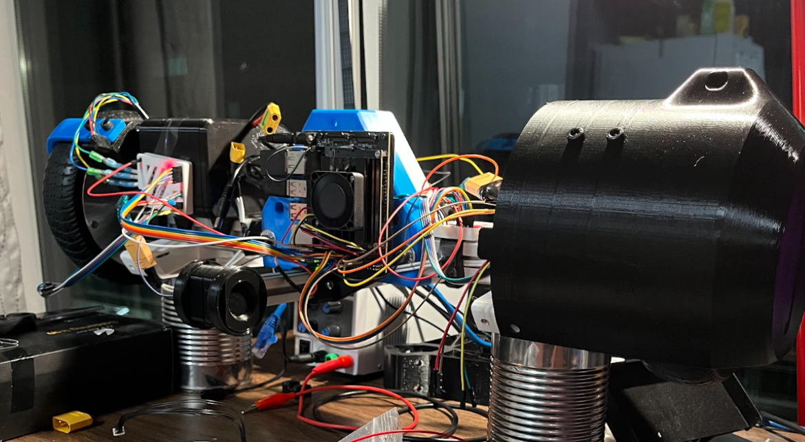
Do we get points for the bean can stand?
Because we used a Nvidia Jetson, we were pretty limited in regards to libraries that would normally come with something like an Arduino or Raspberry Pi. The TMC motor controllers are also not common in hobbyist communities and don’t have any decent public libraries. Avoiding CircuitPython and ROS, we decided to go forward writing our own libraries from scratch. For the IMU (BNO055) and ToF (VL53L0CX) this was straightforward; they both communicate over I2C and return simple data formats.
For the TMC controllers, this was an absolute nightmare. The controllers we ordered had the TMC4671 and TMC6100 on a single PCB, with separate CS lines through SPI. The boot up sequence alone required an intricate timing of address reads and writes to get the chips to play nice with each other. After which, initializing the motor parameters and encoder feedback was another poorly documented minefield. Changing motion modes between flux, torque, position, and velocity was extremely complicated - forgetting to set one address would end up catastrophically imploding the system (which isn’t very fun with 350W motors). Ultimately, we think the firmware might’ve been the downfall of this project - specifically with the motor controllers. We still aren’t sure if it was a bug on the TMC4671 side, or in our firmware, but it prevented us from moving forward with these controllers. Even though our firmware is most likely the problem, we were carefully watching how our code interacted with the registers and with no registers changing, the behavior of the motors would change suddenly.
The semester we were doing this project was also the first time learning basic controls. I remember learning block diagrams in SYDE 351 and then realizing that maybe just maybe I should be drawing one for this problem. I looked through a couple research papers on inverted pendulums and segway control systems and thought “this looks easy” - it was not. It was easy to make it balance, took a couple of educated guesses about control loop organization. It was very hard to make it robust to perturbations, of which on a college campus there could be many. We started with one loop that took a setpoint angle as an input, calculated error with the IMU and output a motor velocity (assuming a linear relationship between pendulum angle and velocity). But, to get it to stand still we had to add a setpoint heuristic that we would calculate on power up (meaning someone had to manually balance the robot on power up). Any tiny error in this set point caused it to slowly want to move, but because of an integer rounding problem, it couldn’t. This means it would just accumulate a ton of integral error, and then move drastically. To get around this, we pass the integral error through a window function to cut it off.
After tuning that loop, another loop was added in series with this. It would take a commanded centroid robot speed (average between left and right motors) and output the angle required to drive at that speed. Then that angle would be fed into the prior loop as the setpoint. At a commanded robot speed of 0, the loop would figure out what the angular set point had to be in order to keep the robot still. The next loop would take that setpoint and find a motor velocity path to get there. A block diagram can be seen below.

It's important to note that the TMC4671 motor controllers had their own control loops baked in. They had cascaded loops around flux, torque, position, and velocity. Once tuned with a step response, they could be written to via the aforementioned byte addresses.
Another unforeseen challenge is that the motor controllers (as mentioned previously) only let us command integer RPMs, meaning that the robot would tip forward a bit until the control loop output 0.5rpm which would get rounded up to 1 and the robot would jolt forward. Then, as it fell backward the same thing would happen, making it oscillate a tiny bit. To get around this we could have added another loop and controlled position instead of velocity, or maybe even torque, but this never got done before we put the project down.
At this point with the motor controllers acting up so much, it became impossible to tune a reliable control system. The robot got scary to work with, often randomly accelerating to high speeds or jolting to a stop, sending a shock through the entire system.
To preface this, I know this is amateur hour - Ivan was supposed to do this part, but I wanted it done fast and he didn’t have the bandwidth to fully commit to the project. The perception code I came up with is not very robust or cutting edge. I did this just with my intuition of what would work and after reading some elementary research papers.
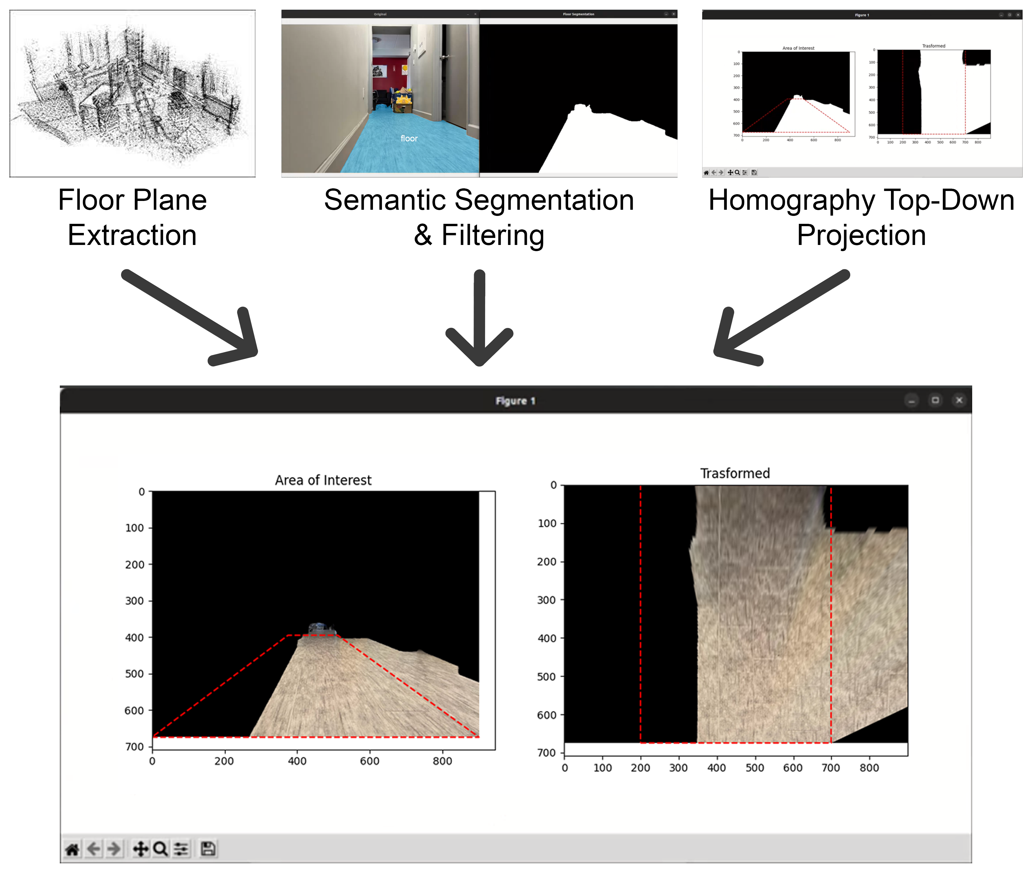
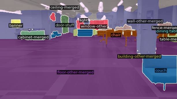
The goal of the perception stack was to build a map of the drivable static environment, while avoiding obstacles dynamically. To build a map of the robot's surroundings, we used ORB-SLAM2 which worked really well even on our small processor. SLAM would be responsible for getting the floor plane, visual odometry, loop closure, and most importantly a ground truth for distances. To interact with our live environment we used a lightweight Mask2Former semantic segmentation model to find the pixels that were on the floor, obstacles, people, and anything else from the vast 137 classes. My thought process on getting the drivable map was to take the floor pixels from the semantic segmentation and project them using homography onto the floor plane (seen below). The projection would be scaled by correlating keypoints from SLAM with the same keypoint in the semantic segmentation. Once we had a 2D map of drivable space, and a way to measure where we were in it with SLAM, a path planning algorithm could be developed or we could simply randomly drive within the space.
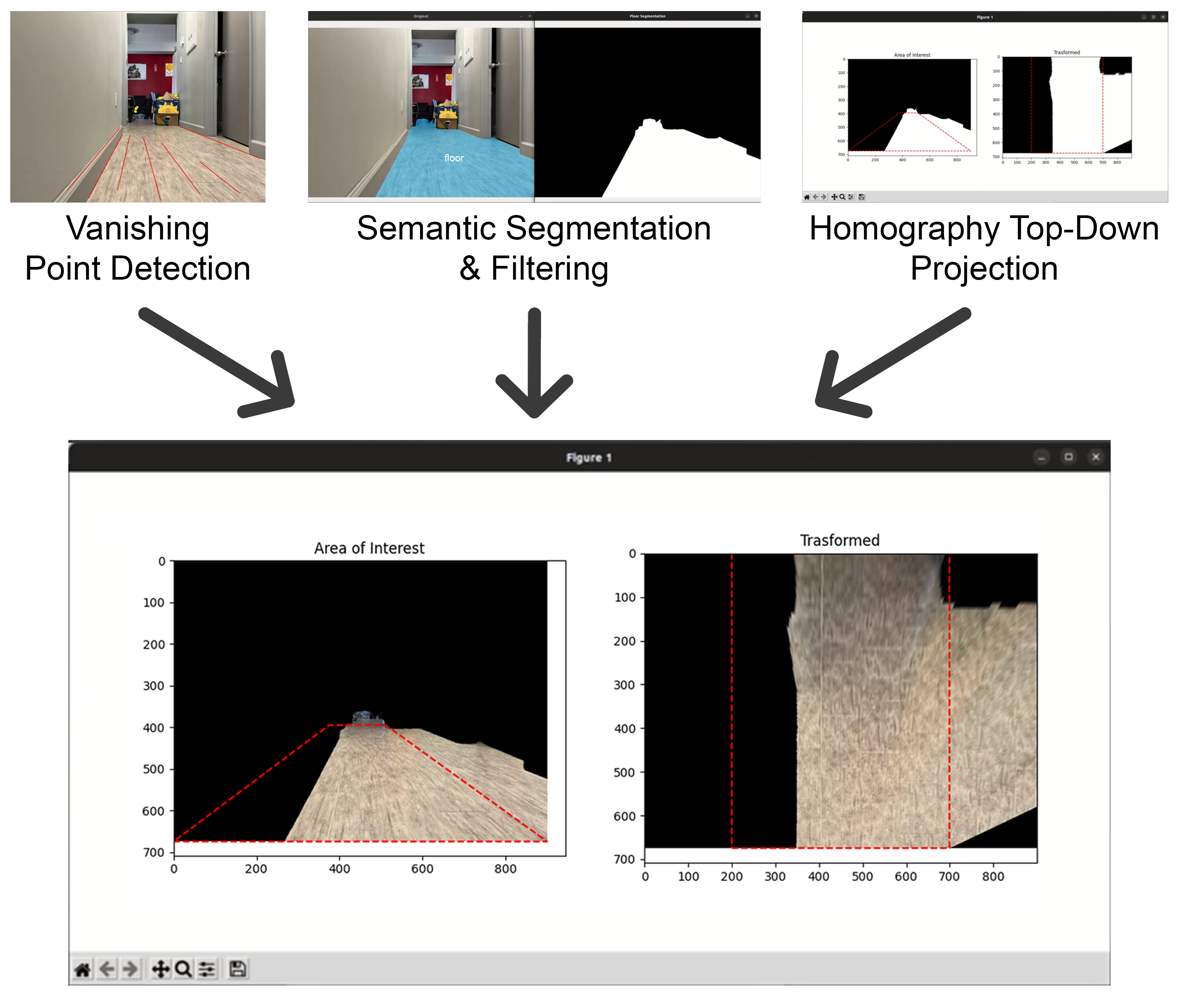
To project the camera feed onto a birds eye view 2D map, we had to find a transform from the camera perspective to the ground plane. My intuition for how to do this was to find the vanishing point, and use a linear transformation to make the vanishing point at infinity, thus getting a top down view of the frame. At first I made a tool to manually sketch lines matching straight edges on a picture, and the tool would compute the vanishing point. Then I realized this wasn’t scalable or robust so I implemented automatic vanishing point detection using Canny edge detection and then a Hough transform to find lines. Lines would then be intersected at many different points, the highest density of points would be considered the vanishing point, which would be defined by the centroid of those points (shown below in blue).

I thought at first that the transformation would only need to be found once, and then could be used for the robot so long as the camera/camera mounting didn’t change. Later I realized how naive this was, as we were making a segway that was constantly swinging about changing the camera angle. To solve this, Ivan added a function to ORB-SLAM2 to find the ground plane using RANSAC. SLAM could then figure out our camera pose relative to this ground plane, making projections much more robust (see below). Although never implemented, SLAM could be used to add up sections of the 2D map slowly over time.
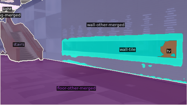
Semantic segmentation enables floor segmentation, as well as lots of useful features for the future. Although not implemented, it would allow us to avoid challenging obstacles such as chairs, stairs, and even animals. It also makes it easy to keep track of people and even follow them. After testing two of the ADE20K SOTA models (BEiT and a model built on SWIN V2) we realized that we would be extremely computationally limited - they were each taking about 4 seconds per image on a GTX1060. We then tested some lighter weight models made for low power applications - namely light-weight RefineNet, RGBX, and a model built on FAIR’s omnivore. These were too unpredictable and failed far too often to be drivable. We settled for something in between, a model called Mask2Former had amazing performance (see below for examples in E5) and ran decently fast. Now since this project didn’t get finished, we never got to try running SLAM, controls, and Mask2Former all at the same time (I’m sure it would’ve been a disaster) so we were actually playing around with the idea of streaming video to a server which could run the semantic segmentation model, and return a masked image of a requested label.
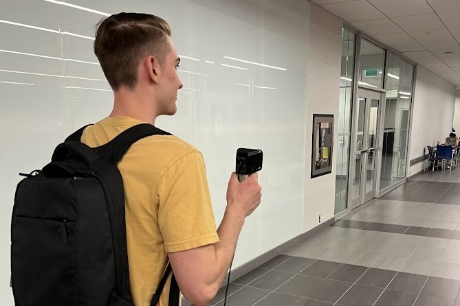
For our SLAM system, ORB-SLAM seemed like the obvious choice. It’s crazy how far ahead it stands compared to other options, super optimized performance and amazing results. To gather calibration data and characterize different cameras, we walked around Waterloo’s E5 building at robot speed holding the camera very steady at robot height. As mentioned previously, the original webcam we wanted to use had horrible stability issues and ORB-SLAM was having a tough time keeping track of keypoints, but after switching to a PiCam everything started to work great. An image of the E5 lobby and data gathering can be seen below.
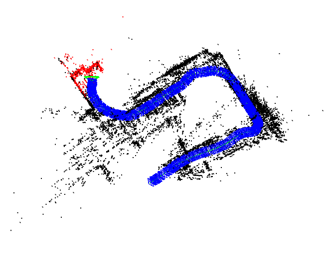
I learned a ton about perception doing this project. I wish I kept going to see what improvements I could make, and what’s possible. One thing still pulls me apart - reading papers gives you a better intuition for what works and what doesn’t work, but it also makes you think in a certain way. It’s this way of thought that might block new, crazy, radical ideas from entering space. I see this in many industries, and it troubles me.
Although an unsuccessful result, it was good to get back to my roots and build a robot. It reminded me of the spark that got me interested in engineering in the first place - there’s something magical about software coming alive in a physical form. I’ll leave you with a video of the last balancing test we did before packing up the project and moving out of Waterloo.

At the start of 3B after our 4 month co-op term when it was time to move in, Ethan brought Bracket Bot with him - partially as a joke. Leaving a robot in the living room of an apartment of engineers is like dangling a carrot in front of a donkey. I wanted to update this post with the work we did because we probably put in 5 times more energy into the project than the previous semester.
This time we happened to have an ODrive V3.6, which was a suitable replacement for the Trinamics. ODrive is (or was) an open source BLDC motor controller project by hobbyists for hobbyists. The new ODrive controllers are closed source and much more expensive sadly, but there is a huge community for the older V3 generation which are completely open source. In a single night we got the motors working with the ODrive, something that took weeks with Trinamic drivers.
We decided that our cascaded PID approach might be too simple to get super robust balancing - something that I later found out to be incorrect but still a step in a good direction. Instead we read some more research papers and kept hearing about LQR and LQG controllers. After reading about them more and studying up on the topic we decided it would be a good thing to try. Ivan became the relevant expert and wrote a simple balancing script in python using pitch angle, pitch rate, wheel position, and wheel velocity as inputs and a wheel torque as a single output. In order for LQR to work we needed an accurate model of our system, including moments of inertia around the principal axis. To do this I meticulously went through each component and compared it's weight to its CAD weight, validating the CAD model.
We started the codebase from scratch, mostly using python. We used the multiprocessing package for communicating between different processes, and boost for communicating between C and python. To run ORB-SLAM even faster, Ethan and Brian found a CUDA accelerated ORB-SLAM library and adapted it to work on our hardware. This allowed ORB-SLAM to run much faster and take up less processing power on the CPU. A video of it running on device in E7 can be seen below.
We also knew we needed a lighter semantic segmentation model, so instead of using Mask2Former we used a smaller SegNet based on FCN-ResNet18. It runs close to 30fps on it's own, but about half as fast when ORB-SLAM is also running. We temporarily aggregate multiple segmentations together to get a better resolution segmentation. A raw output from the model is below.

As mentioned before, the plan was to extract the floor plane from SLAM and then project the floor segmentation onto it - this never really worked before but Ivan and I finally got it working cohesively. The projections can be merged together to make a map of sorts (which ends up looking a lot less intuitive than you may think because of lighting - Google Maps is so much more impressive to me now).
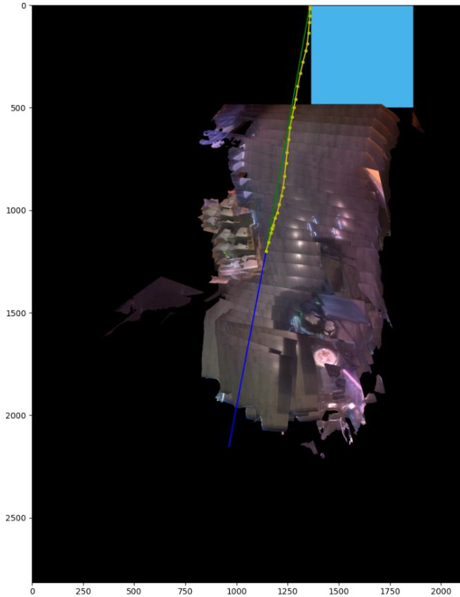
Although the goal was to be completely autonomous, we really wanted a way to pre-program paths. We could even design driving lanes through the university buildings that the robots could stick to. I build a simple tool to draw cubic splines onto maps, it exports waypoints that include acceleration and velocity considerations. Using it on an example map of our apartment can be seen in the image below.

Finally, after a lot of work combining everything, we tried executing the pre-planned paths on the robot. Our apartment was super cluttered so the robot barely fit to begin with, but it did manage to circle our kitchen island.
I happened to meet George at a party in SF, and had to show him Bracket Bot. He thought it was super funny and mentioned how serious they are about robotics at comma - a few months later we got invited to COMMA HACK 4. The hackathon was 48 hours in San Diego, with the main challenge of driving through their office hallways autonomously using a comma body, to a finishing point just outside. I ended up doing two hacks, the first was attaching a custom telescopic arm and suction cup to the comma body to give it beer fetching abilities. Doing hardware at a 48 hour hackathon is a bad idea, right after getting it to work we burnt out a lot of the electronics. The second was solving the autonomous driving challenge with Ivan. We really wanted to take an end to end approach, similar to comma. Building a software stack like what we used on Bracket Bot just wouldn’t cut it, plus I think we learned that more holistic approaches tend to win out in the end. End to end usually would take a ton of data, but we planned to overfit on purpose. We planned on training a model that took in an image from the camera, and output 3 values representing turn left, go straight, and turn right probability. To gather a ton of data quickly, we literally carried the robot around the path while recording video. To capture a ton of out of distribution data we purposefully collected correction data - we would angle the robot to the left to collect “turn right” data - same with the other side. We would then take the model output, and combine the 3 numbers into 2 wheel velocities, allowing us to interpolate between uncertainties.
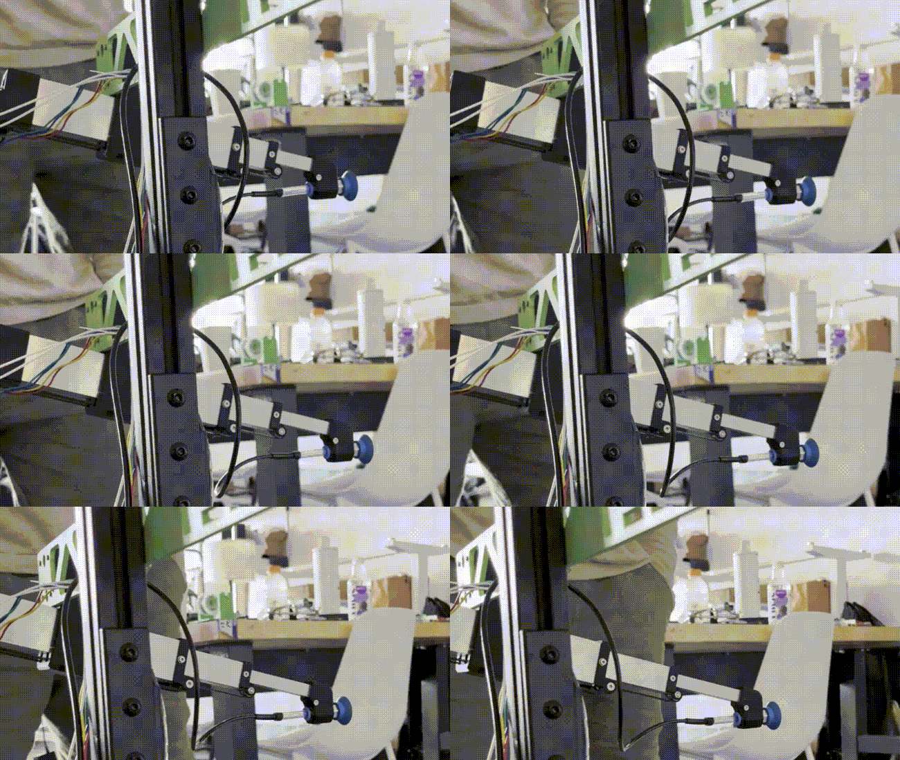
This technique worked shockingly well, in areas it was bad we would just collect more data. It started to break at competition time when the sun was coming through the windows, but we just collected more data. We also had a heuristic that would get it unstuck (since when either wheel hit a wall it would just swing into the wall and get stuck). If a wheel was stuck for more than 2 seconds we would simply back up and turn a bit in the opposite way. If you want to watch our demo, the hackathon was live streamed here.
In late 2024, Brian Machado (who came up with the project) needed a capstone project. He decided he wanted to turn Bracket Bot into something that could be made at scale. Something that anyone could build and develop on, the simplest human-scale mobile robot. His goal was something <$400 that could be assembled easily and quickly in an Ikea like fashion. He rearchitected everything to reduce cost, setup a supply chain in China, and simplified everything to an extreme factor. To prove this out, he ran a hackathon with 40 Bracket Bot kits! People built extremely cool projects, adding arms to the robots, adding speech and facial recognition, and autonomously navigating through the engineering building. This is the start of a new community of robotics.
It's extremely cool to see where this project went, on so many occasions I thought the project was over and it made me sad. Brian brought it to a whole new level, building things at scale is very difficult, including communities. Brian plans on selling these kits and improving the project after graduation, you can support him at bracket.bot