Cycloidal Actuator
Custom double cycloidal gearbox designed for robotics
As robotics grows as an industry, physical interaction with the real world is becoming more and more crucial. Lots of interesting design problems come up when designing robots for a world made for humans. Some examples would be touching and feeling surfaces, pushing and pulling things, balancing objects and much more. One of the largest problems with physical interaction i’ve identified over the last 6 years of working with robotics is that making compact, cheap, powerful actuators is really hard. With the emergence of cheap and easily accessible hobby brushless motors it's almost hard to ignore that they are a perfect solution for this problem, except for one small thing; they’re really, really fast. To make a usable actuator (rotational or linear) out of them, some sort of reduction needs to be implemented, as typically they run over 10,000 rpm with relatively low torque.
I knew I wanted to use my new CNC router, along with my 3D printer to try and come up with a versatile solution to this problem, so I started laying out the groundwork. I would need to come up with a mechanical reduction to provide a low speed, low backlash, high torque output.
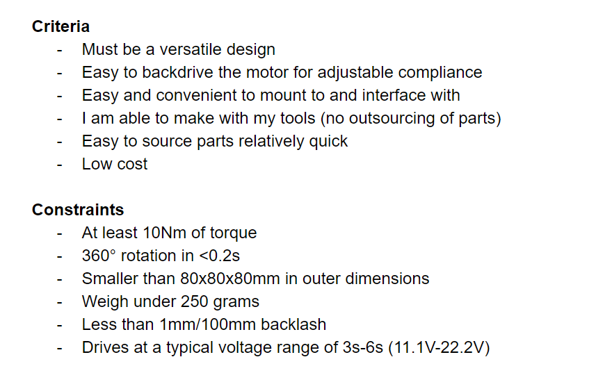
With these criteria and constraints I started choosing reasonable parts and locking down some variables. The first thing I wanted to pick was the BLDC motor, with the main criteria being a low KV, and a small size. When it comes to low KV motors the selection is pretty small, and the Tarot 4008 motor stands out as the best power to size ratio when compared to others. This motor has a 300kv speed and around 500W peak power, and if I want to drive it at a maximum of 6s (~22.2V) that means a speed of ~6660rpm. To get 10Nm of torque I would need a reduction of 20:1 or more (assuming ~80% efficiency), and to turn a full rotation in 0.2s I would need a reduction of 22:1 or less. Picking a middle ground I decided to go with a 20:1 reduction, leading me to a trade study of what type of reduction to go with given my manufacturing capabilities:
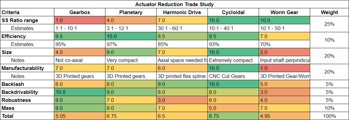
This trade study has lots of assumptions and estimations, but that being said the cycloidal drive has the highest score by a sizable margin. I also like the idea of making a cycloidal drive because it means I can mill my own parts on my custom CNC router, since the teeth are round and there are no small internal corners like in a spur gear. From here I began studying how cycloidal drives work, how different parameters change different factors, and what some typical design rules are. Some cycloidal drives use multiple cycloidal discs offset by a certain angle to decrease the backlash, and reduce imbalance. I decided to go with 2 discs to keep things a bit more simple but decrease backlash that could be caused by my loose manufacturing tolerances. I started designing the gearbox with a layout sketch to determine the rough size of all the parts and what space the actual cycloidal geometry would be limited to.
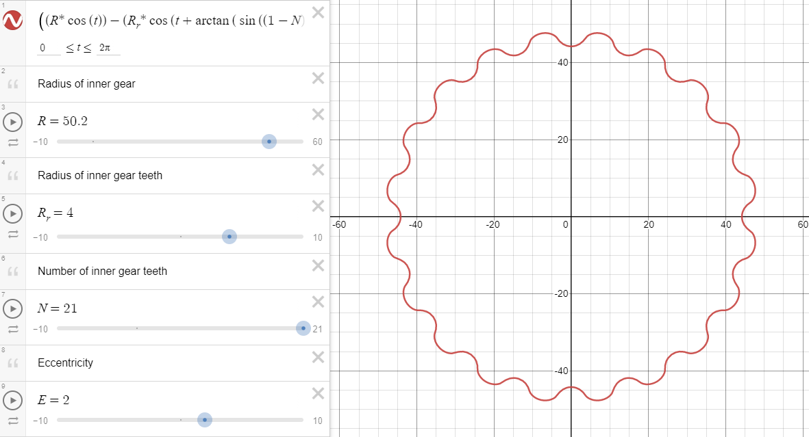
Cycloidal geometry can be represented by a parametric equation when given parameters of the inner ring gear and the eccentricity. I was limited by the internal radius I could cut on my CNC (3mm ideally) as well as some geometry constraints (less than 80mm diameter to meet project constraints). When I was satisfied with the geometry I imported it into Solidworks and started designing.
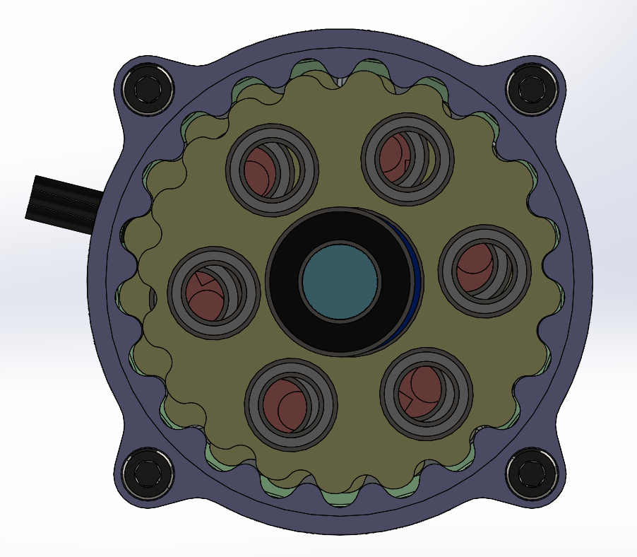
The cycloidal discs then get 6 holes for bearings to transmit their rotation to the pins, as well as a center hole for the center bearing. I decided to use bearings over bushings to transmit the rotation to the pins since I wanted a really low rolling resistance at high speeds, for good backdrivability. The speed of the pins running in the bearings is also relatively high, since it is the same speed as the motor, so it makes more sense to use bearings.
The design of the inner ring gear is much more simple, the tooth geometry is just a semicircle and connecting them is a “valley” that provides clearance for the cycloidal teeth as it rolls. On one side a ring bearing gets press fit in to hold the output plate.
The two cycloidal discs and inner cycloidal gear are the only parts cut on my CNC out of 6061. Although I would’ve liked to make the central camshaft out of aluminum or steel, it's a challenging part to fixture and machine. Because of this I printed it out of PETG, which despite being a compromise ended up working really well. Since FDM 3D printing has anisotropic (and unpredictable) properties I used an empirical testing jig to determine the ultimate shear strength of the shaft, and the coupling (seen below).
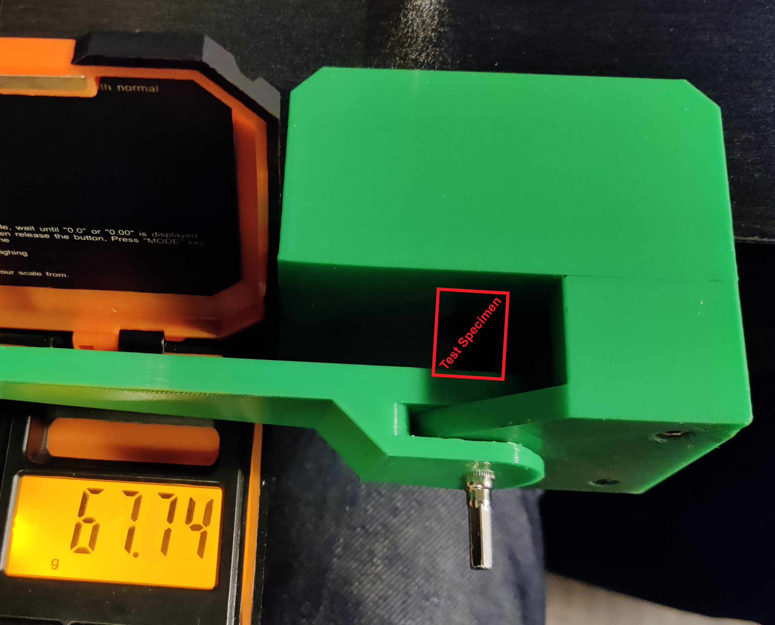
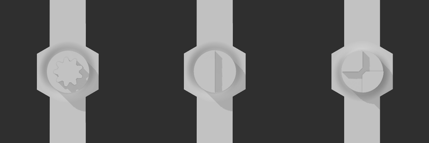
The shaft could easily handle the 0.63Nm max torque of the motor, as it survived well above 2Nm. The coupling however became a big problem, the first design only held 0.3Nm before shearing. At first I tried generating different designs and testing them, such as a quarter circle, semi circle, and a spline (seen below, keep in mind they all go into a sleeve, so that they can’t just deflect). The quarter circle had the best results, shearing at around 1.2Nm. This still wasn’t great, considering it's less than 2x the motors peak torque, and with the heat and cycling of this part it is probably the first failure point of this actuator design. Currently I am looking into making it out of a nylon carbon fiber blend filament that has much better strength properties.
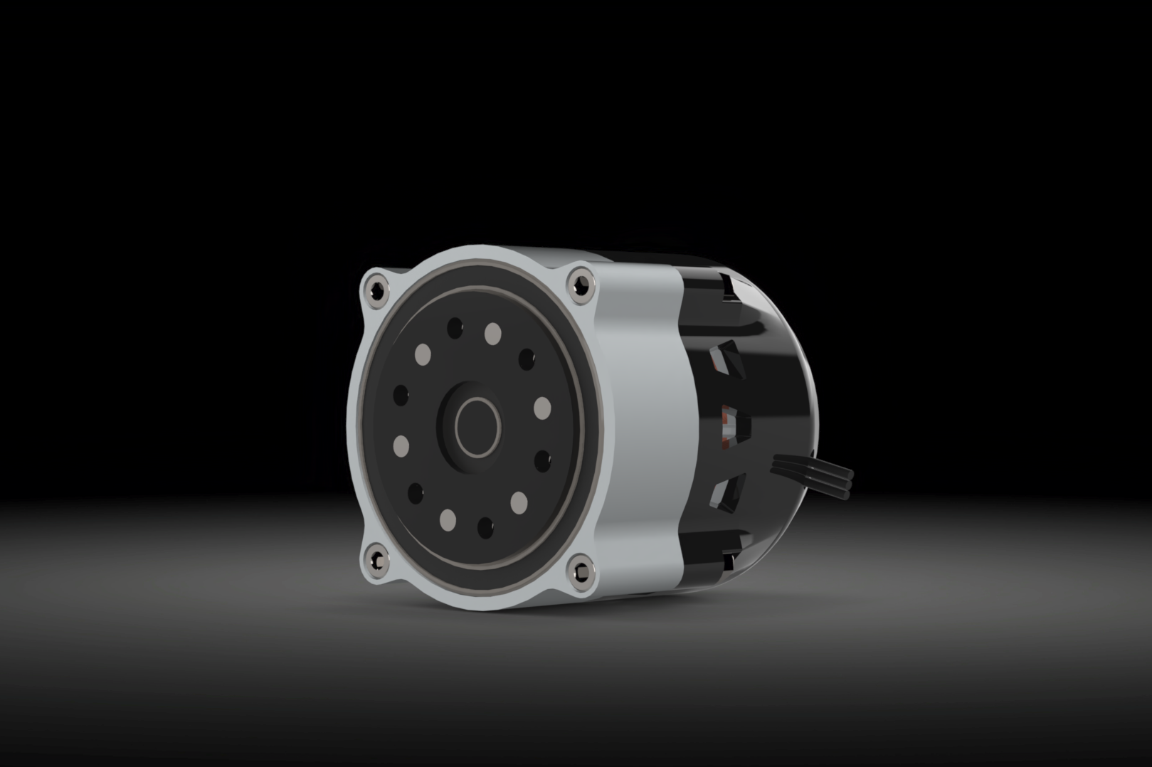
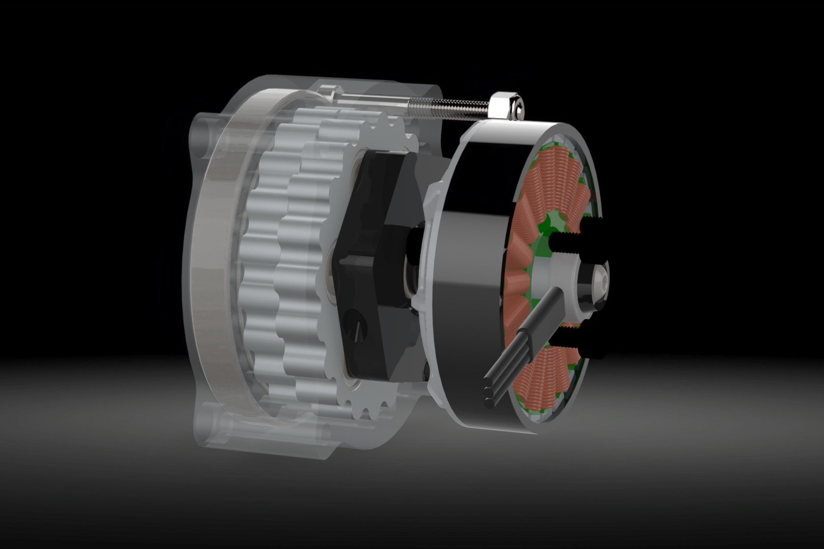
A drawing showing the full actuator design can be seen below, with parts labelled. The final dimensions came out to be 57x54x54mm and the actuator weighs in at 236g.
Some more renders and an animation can be seen below, rendered in SolidWorks Visualize.
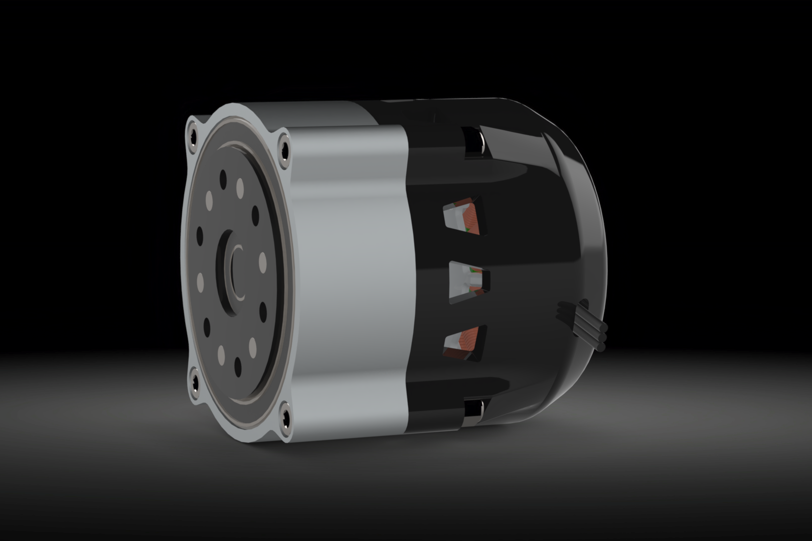
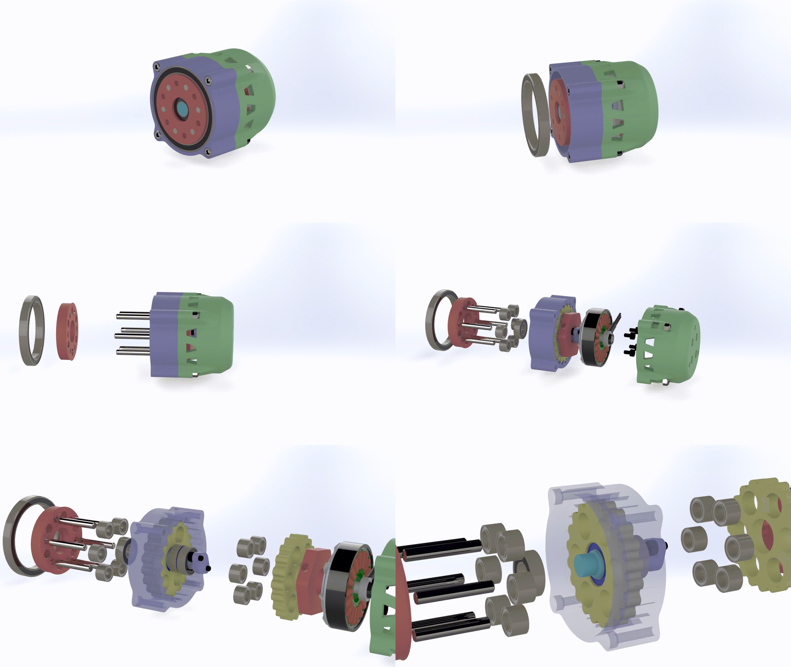
After designing the actuator I started manufacturing it, keeping in mind that I might have to do multiple iterations. I sourced all the parts I needed, including 6061 stock and PETG filament. To cut the aluminum on my CNC router I used a 2 flute 3mm and 6mm end mill with cutting fluid, low feed rates and a medium-high speed. Pictures of the milling process can be seen below.
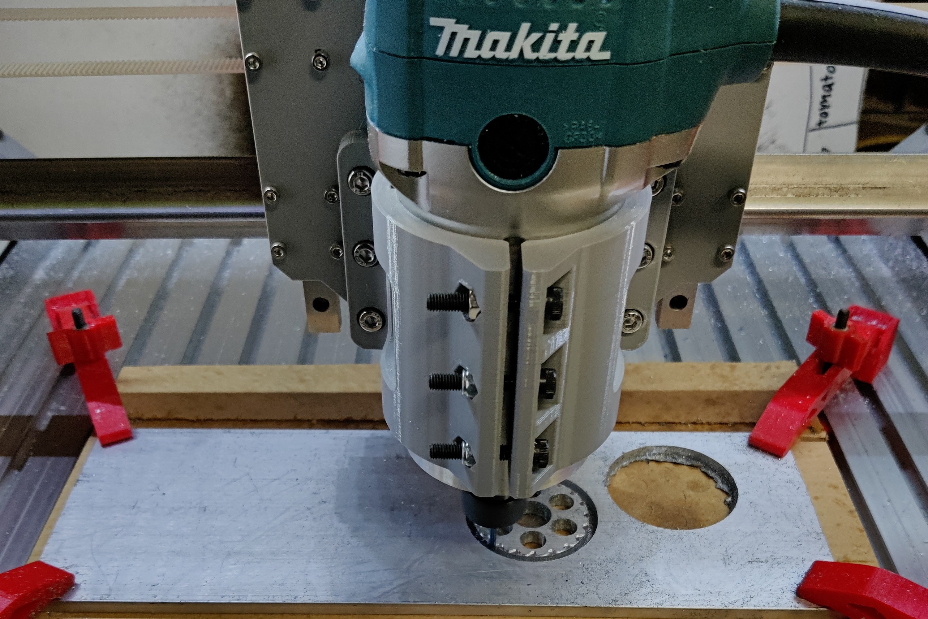
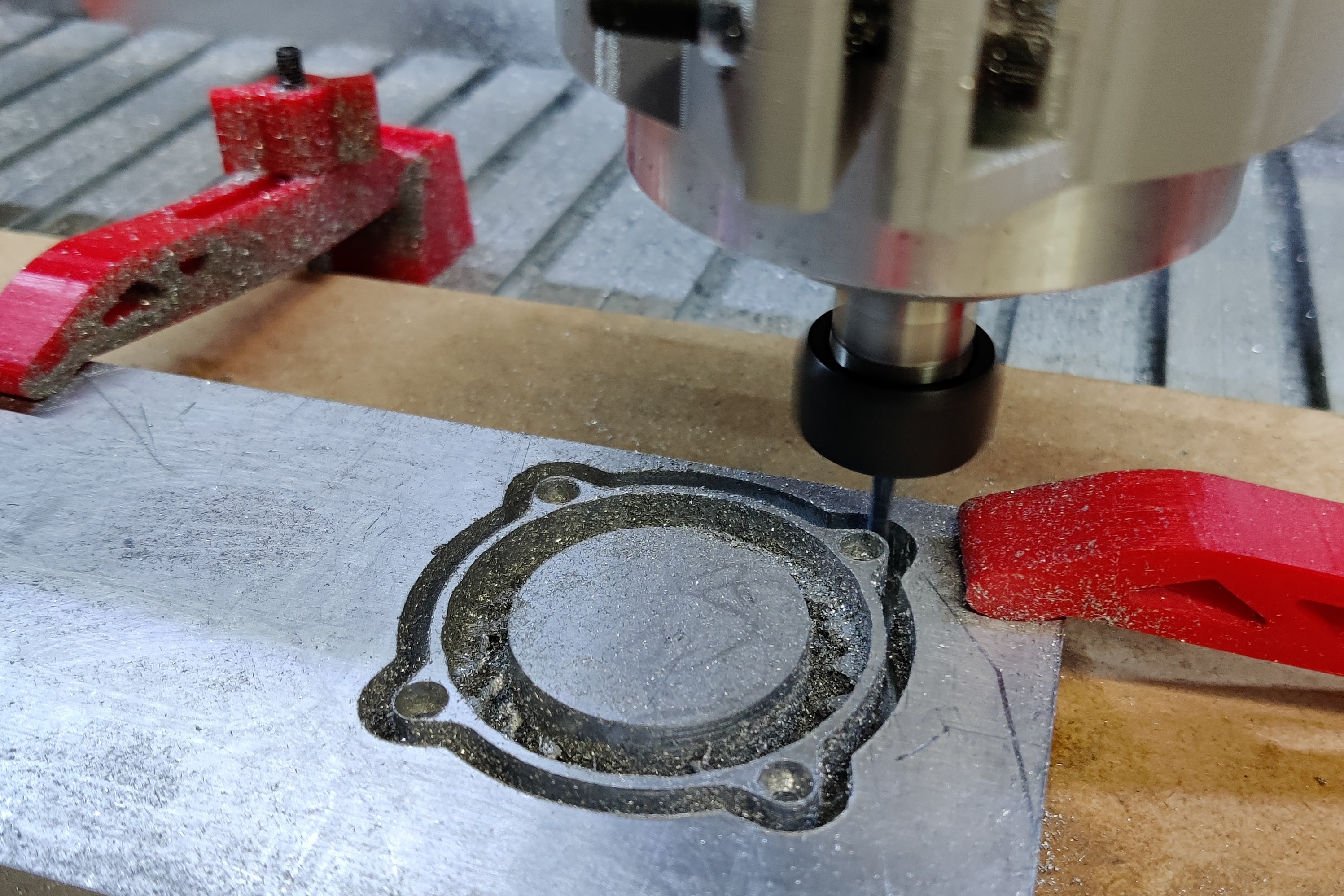
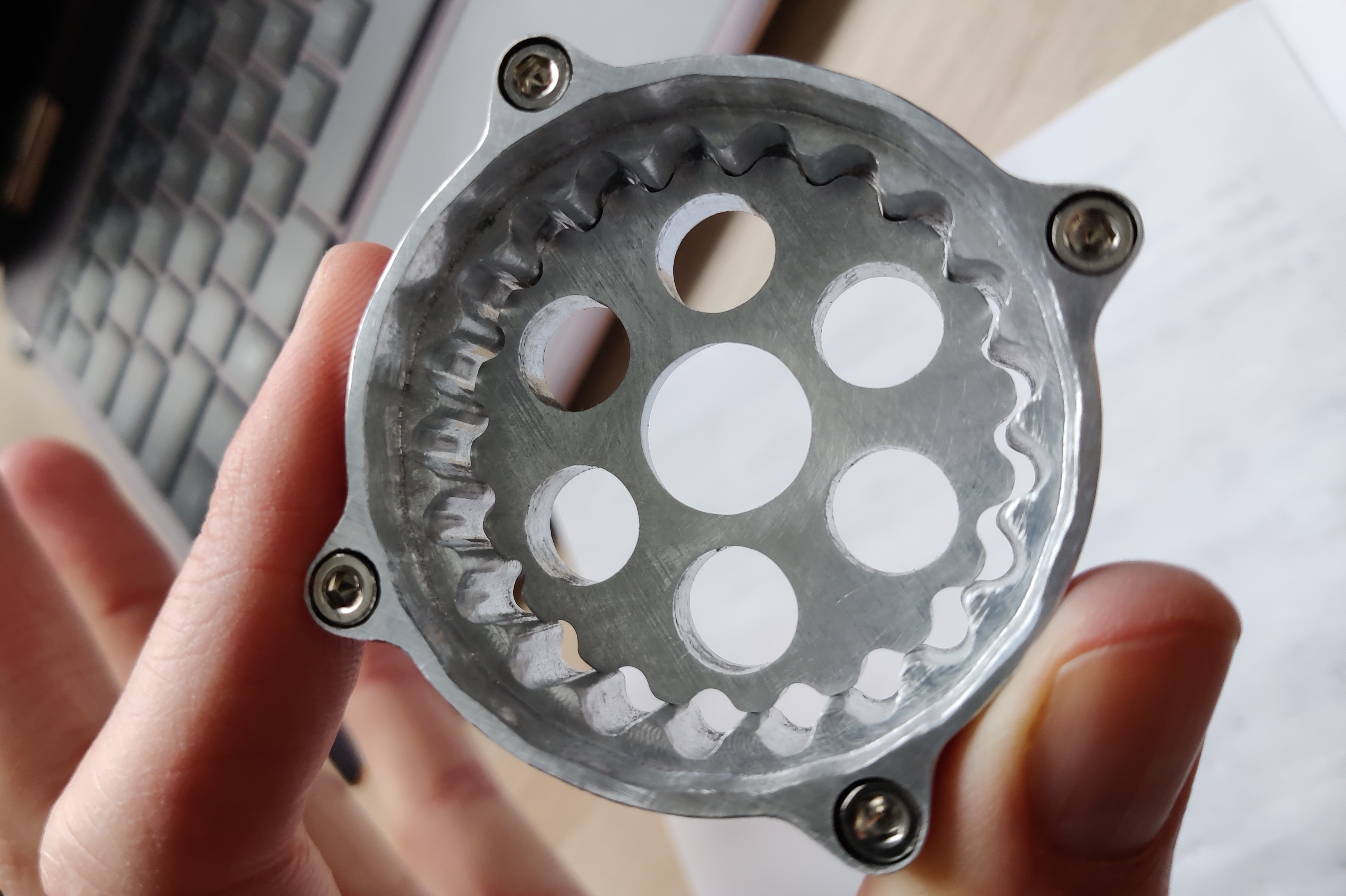
This was the first time cutting aluminum on my CNC router, I had only done test cuts before. Overall I am extremely happy with the results, the finish is a lot better than I expected. The tolerances were around ±4thou which despite being better than expected caused some minor assembly issues and some reworking. The biggest issue I had was with the ring bearing hole, (the large bore on the inner ring gear) it came out as a 24 sided polygon which is partially visible in the rightmost photo above. After some root cause analysis I found out it has to do with my CAM software output settings, and I have mitigated the issue for future jobs.
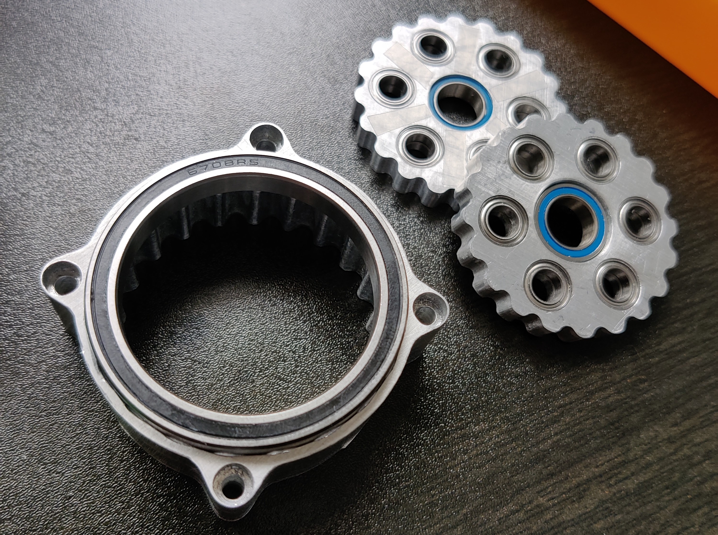
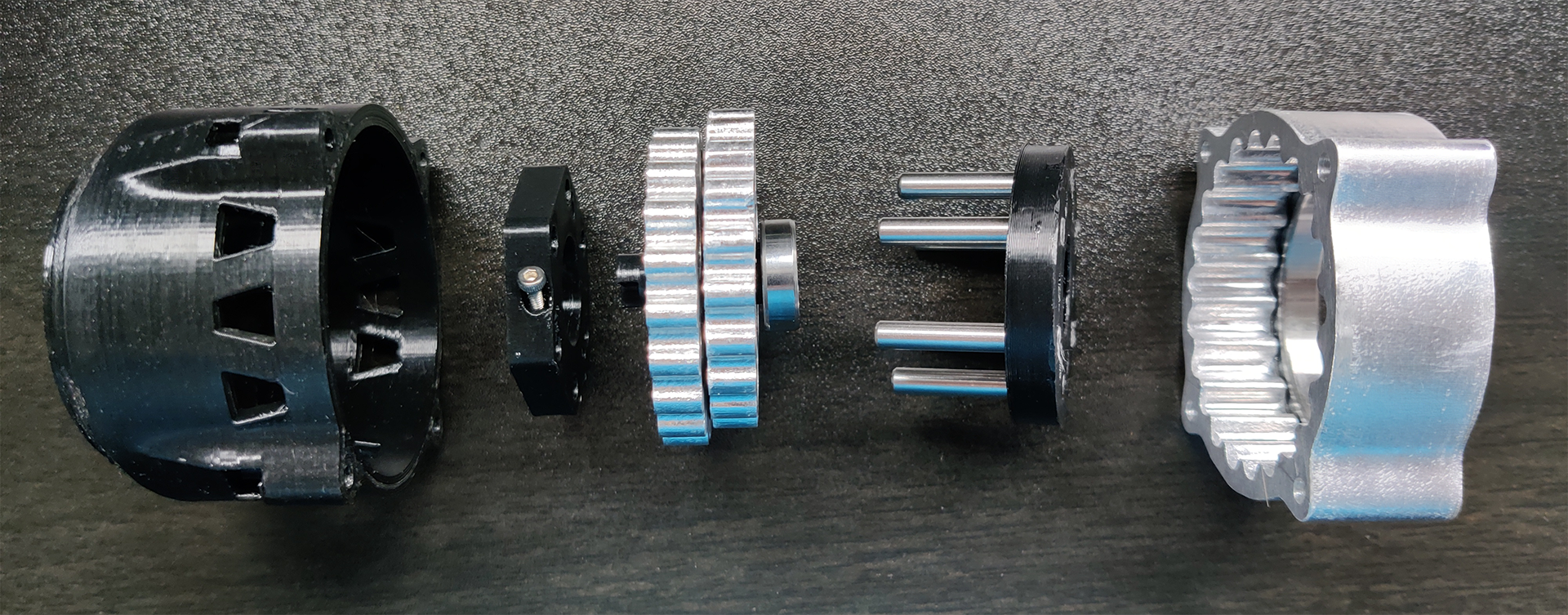
With the custom parts made and the off the shelf components arriving I started the assembly process. I started by cleaning up some of the burrs and edges on the parts, and then press fitting the bearings into place. The next step was to start fitting the other parts together and making sure everything lined up nicely. A “knolling” photo of what this looks like can be seen below.
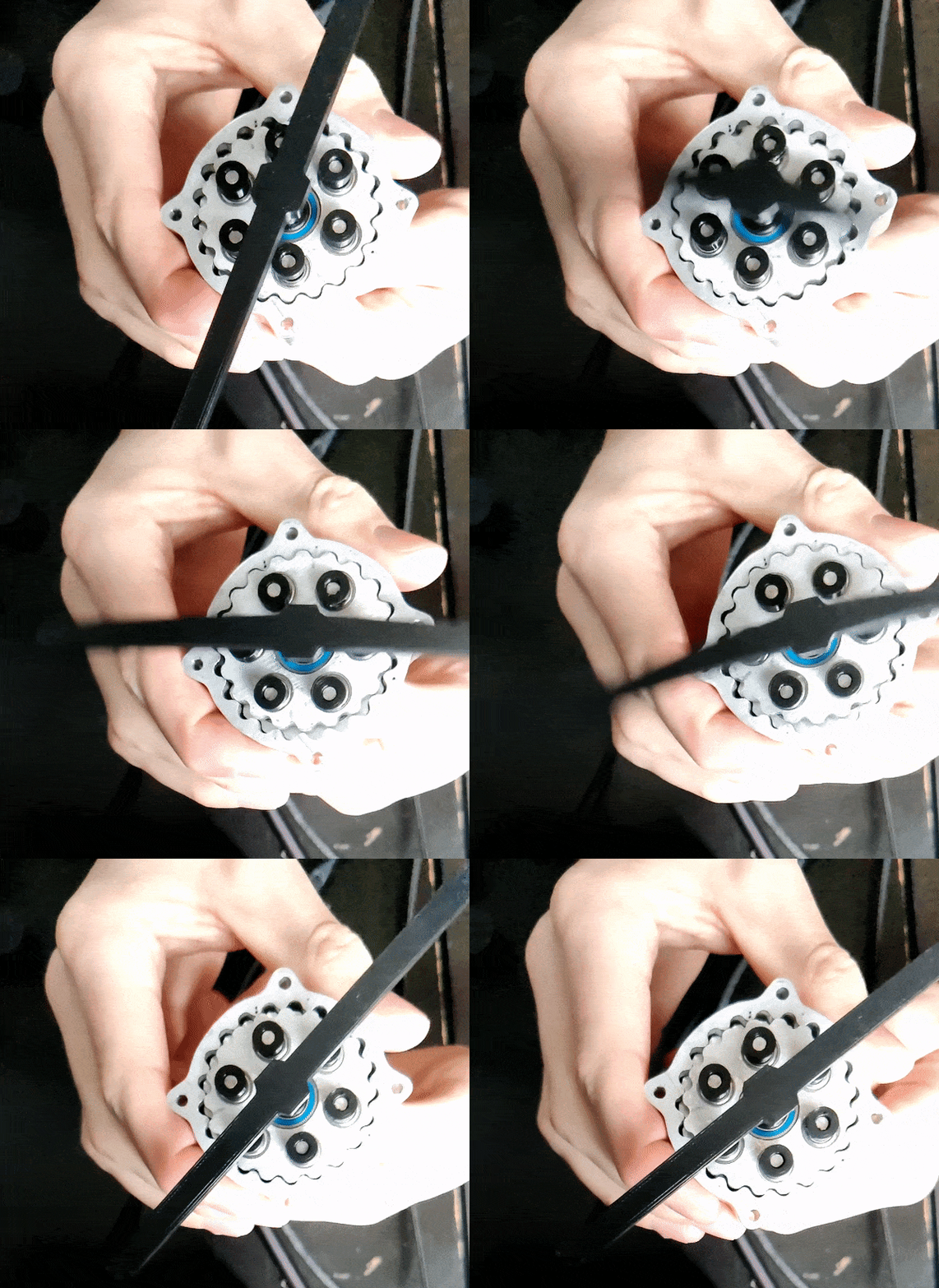
Before adding the motor and motor casing to the cycloidal subassembly I lubricated it and tested backdrivability. The results were really impressive, it is quite easy to backdrive the gearbox despite being 20:1, a 16x slow-mo GIF can be seen below. It is clear to see just how well the cycloidal discs fit in the inner gear, and the second cycloidal disc can be seen behind the one in the front, 180 degrees out of phase.
Finally I put the motor and motor casing on. I ran some powered tests with a DC power supply and an ESC, and they turned out really well (seen below). My only gripe is that there is a minimum RPM I need to go to get it to spin. This is because at low RPM the motor isn’t operating near it's max power and has relatively low torque. This low torque isn’t quite enough to overcome the friction in the gearbox. Because of this the speed range of the motor that has worked so far is 1800rpm-6660rpm. This results in an output shaft speed of 90rpm-333rpm which I am still quite happy with.
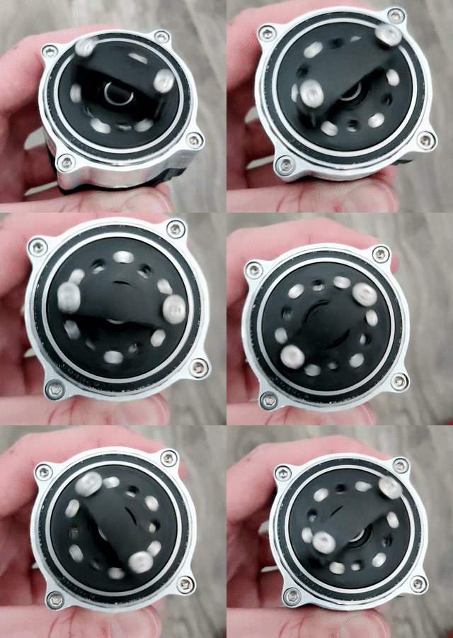
To verify that the actuator meets the criteria and constraints laid out in the beginning I ran a variety of tests and measurements as well as qualitative observations. I believe the design is very versatile, having a small and cube like form factor, with mounting features on the front and back. The actuator is also very easy to backdrive, and although I didn’t have a quantitative measurement of it, it is more than enough for my needs. The parts were all made in house, sourced relatively quickly, and the actuator cost under $60. The first quantitative test was making sure it met the torque requirements. To do this I used a 1m lever arm and mounted it to the actuator, I then continuously added water to a bucket until it reached 10Nm (~1L of water). Using the same test setup without the mass, I found the backlash to be much lower than 1mm. The speed can be verified using slow motion, and counting the frames it takes to do one rotation the rpm can be found to be ~290. Despite not meeting the constraint it is still very close, within 4% and good enough for my needs. I believe it is because of friction in the system that was hard to account for, and I should’ve added more of a safety factor when choosing the reduction. Finally the actuator came in at 57x54x54mm and it weighs in at 236g, meeting the constraints.