UW Formula Motorsports
Design team competing in the international Formula SAE competition
When I first came to Waterloo, we had a session to learn about all the student design teams so that we could explore our options. When I talked to members of the Formula Motorsports team, I was instantly hooked. It seemed a lot like FRC from high school, which I was very involved in, so I decided to go. In my first semester, I really wanted to go every week, but due to my schedule it was challenging. But more and more, I started taking on more tasks and gaining responsibility on the team. I decided to join the suspension team, as it has lots of dynamic moving parts and greatly affects the car's performance.
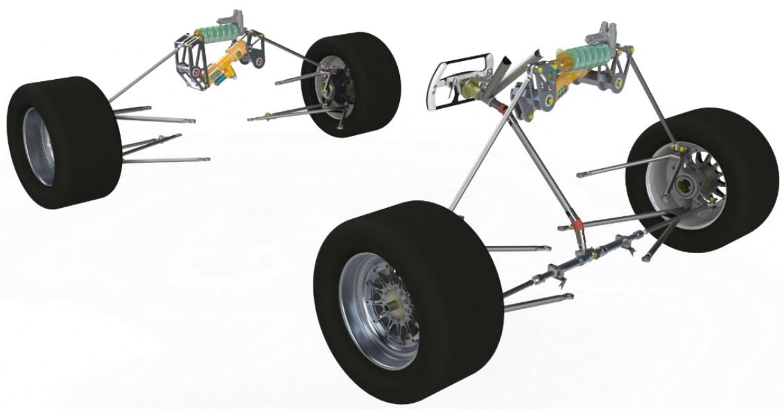
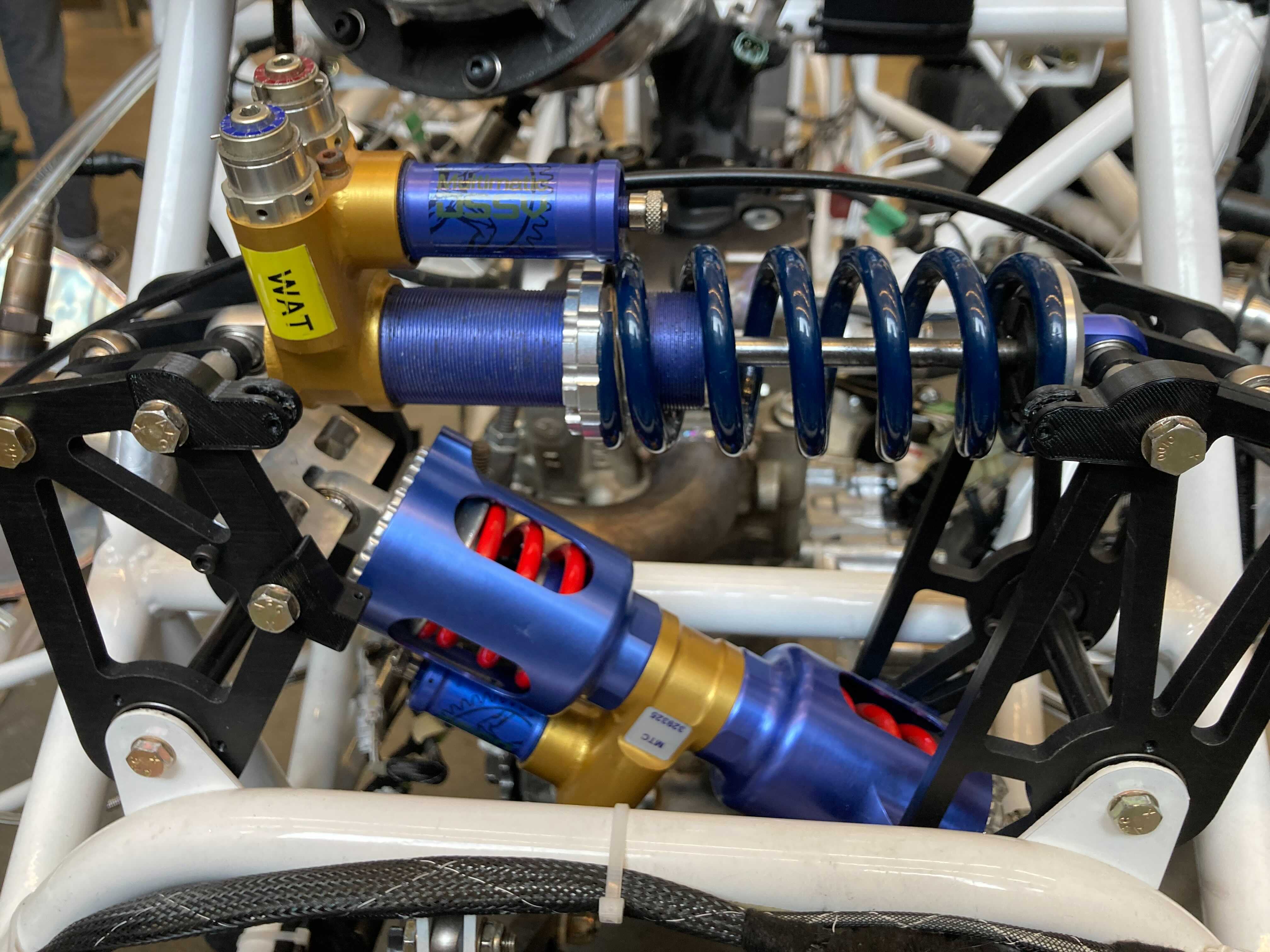
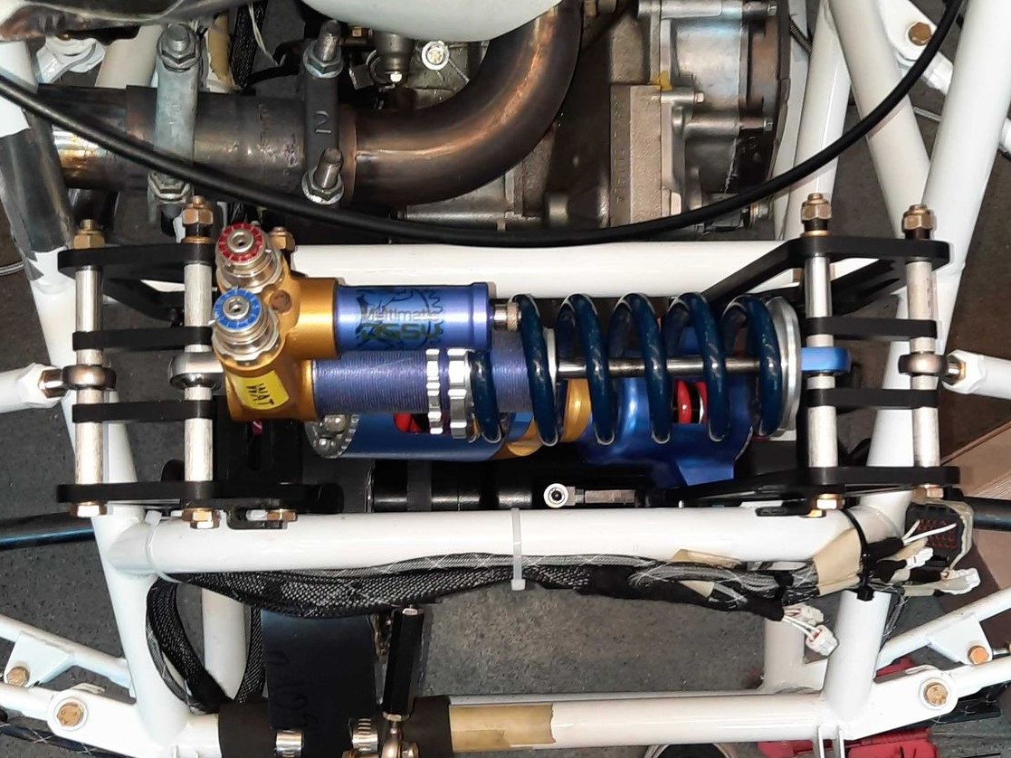
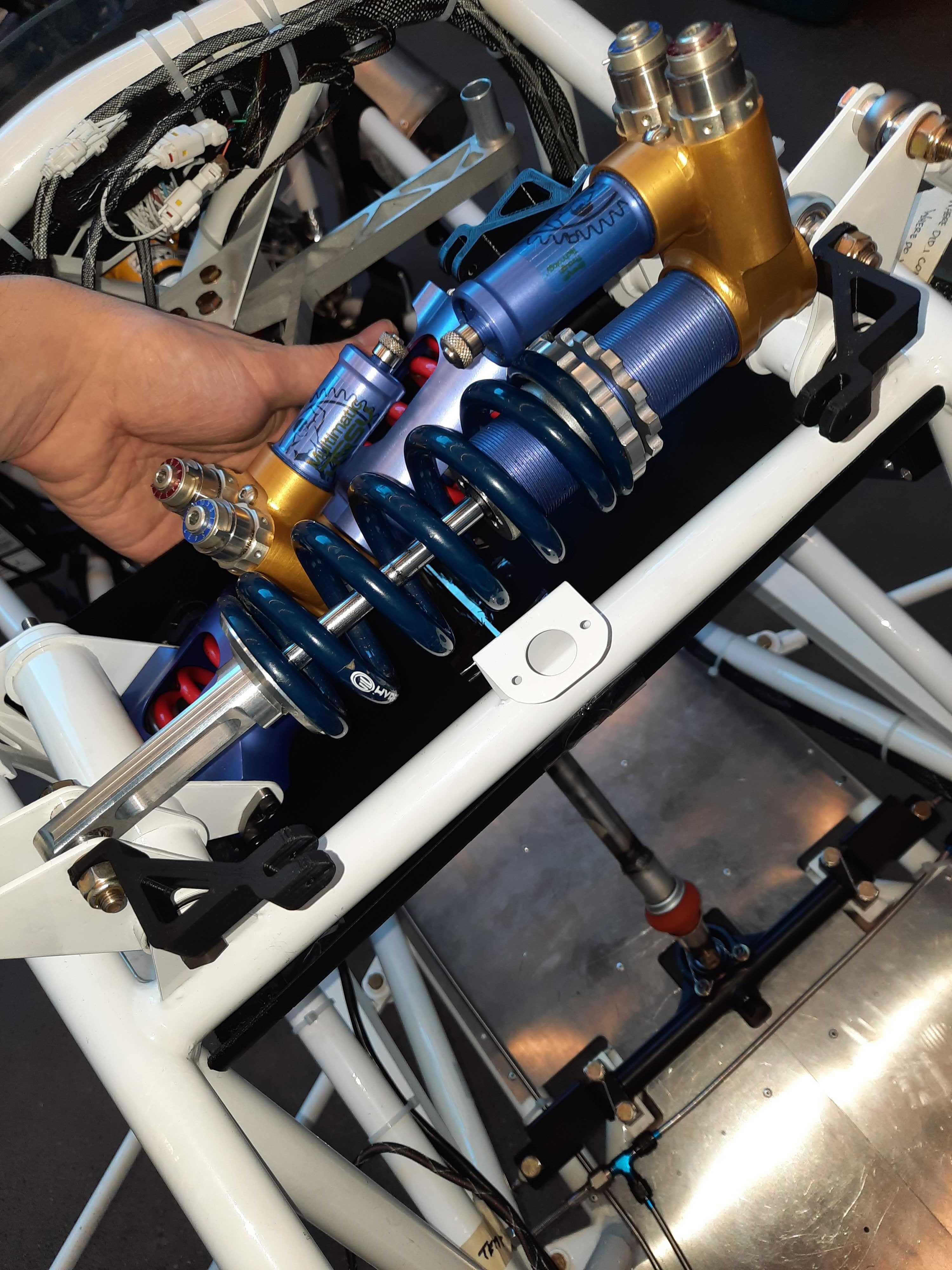
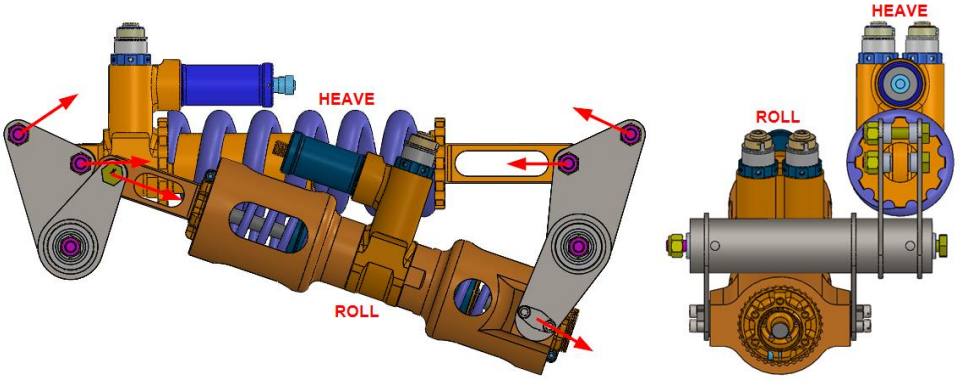
Previously I worked on the 2021 car suspension, and helped make sure everything was ready to go for manufacturing and assembly. The pushrod suspension is constructed out of a lot of hollow tubing, with spherical rod ends used as pivots, giving the tyres an unconstrained vertical motion. The suspension A-arms attach to the wheel and go up to a bell crank that compresses a shock, constraining the system. The roll suspension is also integrated into the bellcrank by having two asymmetrical levers. This way, if both tyres heave at the same rate, the roll suspension doesn’t compress. But, if there is more force on one side than the other, the roll suspension starts reacting back. The design (seen above) is compact and works well in practice.
My most recent project on the team was solely designing the new front and rear bellcranks on the 2022 car. Bellcranks take a (roughly) linear motion from the pushrods, and turn it into a rotational motion, which then gets converted into a linear compression of either the heave or roll damper. As mentioned earlier, we wanted to have a roll-heave decoupled suspension style, as seen below.
From the 2021 car, we knew that the rear bellcranks worked really well and were easy to assemble, the only possible improvement was making them smaller so that they were easier to package. The front suspension however has two layers so that it isn’t as tall as the rear, and this requires transferring a large amount of torque through the bellcrank pivot tube. Previously this was done by press-fitting the bellcrank plates onto a hex shaped shaft that would bear all the moment loads. This made assembly extremely difficult and cumbersome. They were also very chunky and blocked the drivers view as well as not being very aerodynamically streamlined.
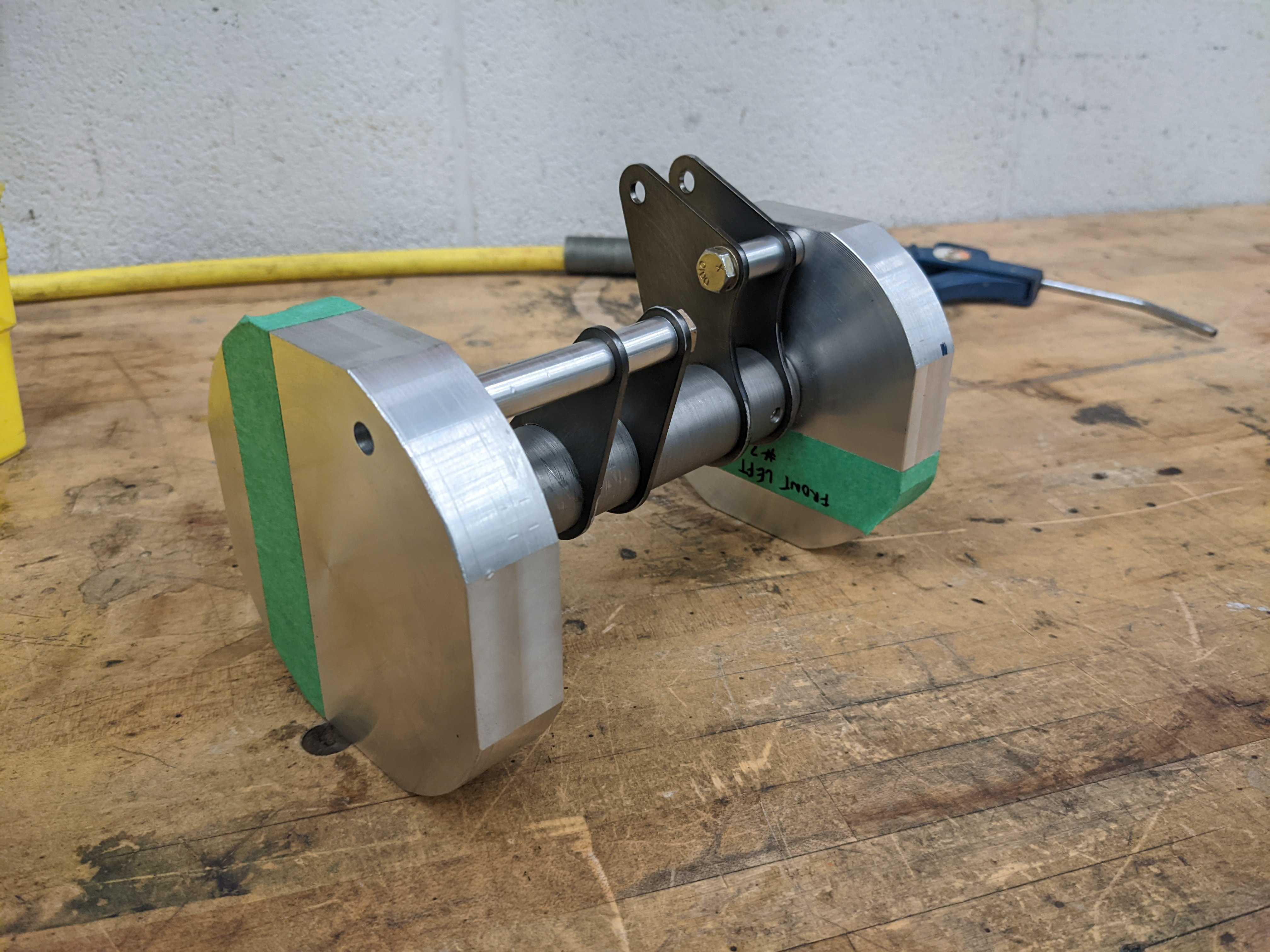
Three options were considered, welding the aluminum plates onto an aluminum tube, converting to alloy steel and also welding onto a tube, or CNC machining the bellcranks from a solid piece of billet aluminum. Welding aluminum was out of the question, due to the poor mechanical properties of welded aluminum and the HAZ. Machining the bellcranks from a solid piece of aluminum was also challenging to design for, would be very expensive, and we did not have the sponsorship at the time to take on such a project. This left the last option, converting to steel bellcranks, which the team didn’t have any experience with. After running some FEA simulations on plate thickness and doing hand calculations for weld strength, it was determined to be very feasible. The biggest concern was warpage of the plates and the tube after welding. To help mitigate this, a fellow team member designed a beefy welding fixture (seen below) to hold all the plates in the correct spots while welding. We also decided to post machine critical features, like the bearing bores in the ends, after welding.
As for the actual design of the bellcranks, I started with one of our team's many MATLAB scripts for analyzing car kinematics. The script in question takes hardpoints as an input, and graphs the motion ratio over the car's heave and roll variations, to get an idea for how consistent the motion ratio is. The kinematics team preferred a constant motion ratio over the suspension travel, as it makes analysis much easier to treat it as a linear system. Because of this, I added functions to the script that quantify how consistent the motion ratio is over the suspension travel, and used that metric to optimize positioning of various pivot points. This was a conflicting goal with my miniaturization of the bellcranks, since by making them smaller, they become more non-linear (because they rotate more per linear movement). I found a balance that shrunk the size of the pivot arms by ~40% (resulting in a total size reduction of 20%), yet was still acceptable kinematically. By doing this, the mass was also decreased on both the front and rear bellcranks by ~30%.
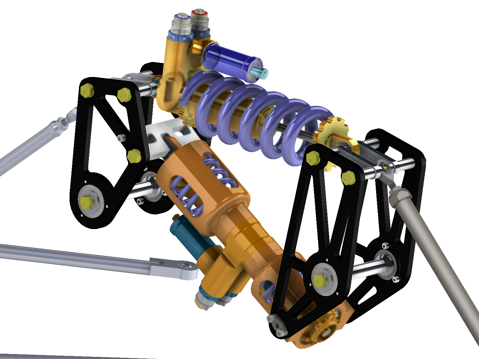
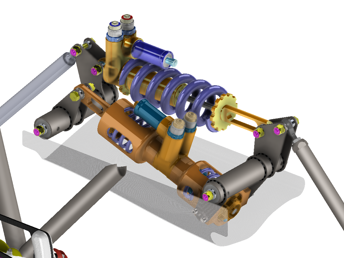
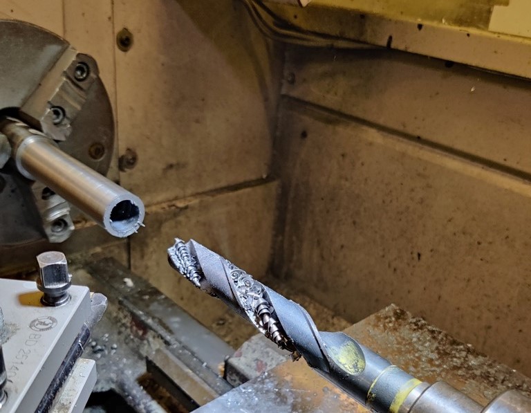
Although I wasn’t able to assemble the bellcranks myself since I was on my work term in California, I was able to machine all of the non-plate components (front bellcrank tube seen below).
Some pictures of the final product after anodizing/powder coating can be seen below. The bellcranks are fully functional and are already holding up great in early testing!
