Introduction
My projects normally start as solutions to problems in my life, where I am not satisfied with the current solution. In this case, I have always had trouble waking up. Al*rms give me headaches, and eventually my subconscious monkey brain learns how to club my arm at my phone to precisely hit the “Stop” button - that is fumble around with it until the noise stops. I’ve attempted, and written, about making a light based al*rm clock in the past with LEDs, but this is challenging and an unnatural solution in my opinion.
Reasoning
From a primal perspective, if we think about how cave men and even animals wakeup, it is purely based on a daylight cycle, and doesn’t involve al*rms at all. Daylight is subtle enough that it will only wake you up when you’re in a light, easy to wake state.
It is widely known that it is best to wake up in a light sleep state, and after a REM period. Studies from sleep scientists including Matthew Walker and Andrew Huberman show that it is more beneficial to your sleep cycle to wake up during these times, as opposed to waking up after exactly X amount of hours. To do this properly, a wakeup signal needs to be just disturbing enough to wake you up in a light state, but not in a REM or deep state.
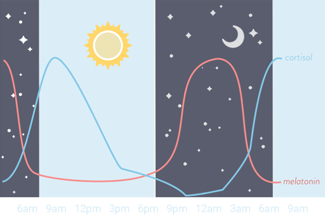
In addition to this, light has been shown to be very important to the wakeup cycle. Andrew Huberman suggests daylight every morning, quoted as saying “If sunlight reaches your eyes soon after you wake, it triggers a neural circuit that controls the timing of the hormones cortisol and melatonin, which affect sleep”. I believe that waking up to an al*rm sound is extremely bad for your wake up cycle, and I can personally say that obnoxious noises just cause headaches, and eventually you just get used to ignoring them.
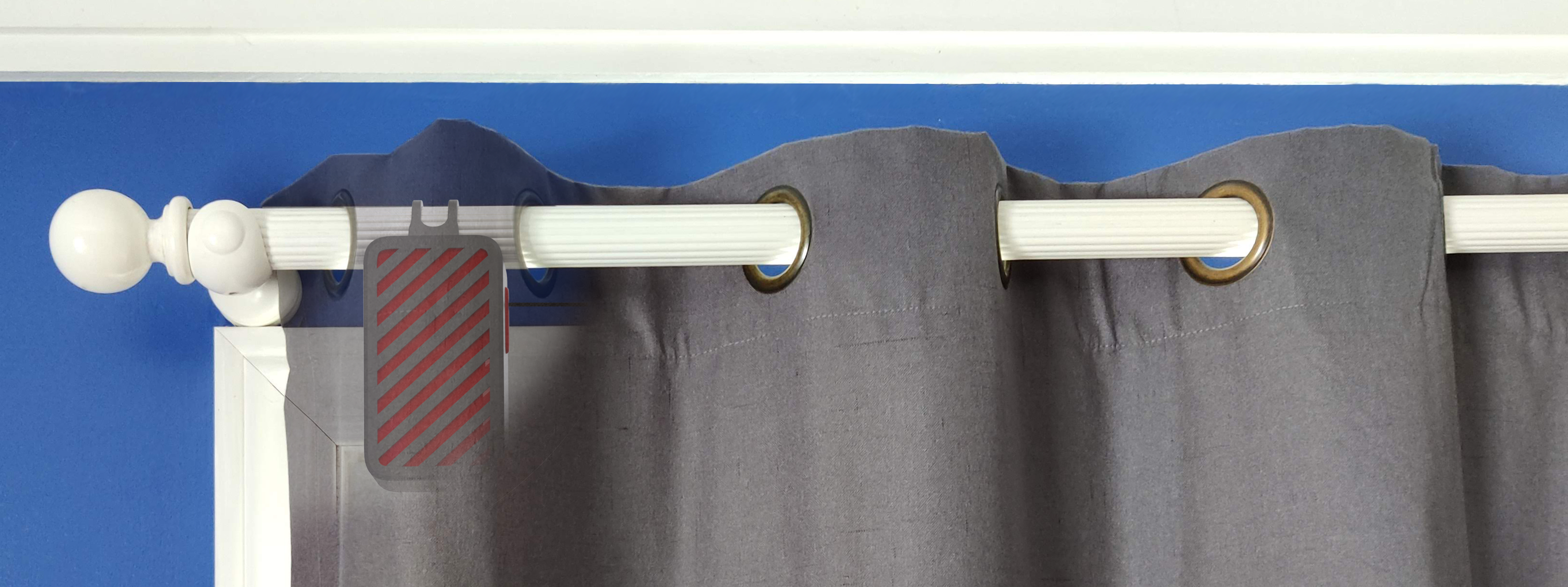
This is why I decided to build Kurt. A curtain opener that makes smart, informed decisions about your sleep cycle to wake you up with natural light and calming noises. Unlike current robotic curtain openers, Kurt is first an al*rm clock, and second a smart home appliance. Kurt can only open your blinds, not close them. This is on purpose, manually closing your blinds sends an automatic signal to Kurt to let it know you are going to sleep soon. From that point, your desired sleep time is measured, after which your curtains are opened and you can wake up peacefully.
Requirements
As typical with my projects, I start by outlining the requirements, and then derive meaning from them to drive the design. These requirements are generated from what I believe to be the MLP (Minimum Lovable Product), and are mostly based on my personal wants.
Product Requirements
Design Input
⠀↳ User sampling shows under 5 seconds is the sweet spot
⠀↳ Curtain store availability shows that 92% of curtains are <60”
⠀↳ Able to draw curtains up to 60”
⠀↳ Onboard loudspeaker, qualitatively louder than smartphone
⠀↳ Some sort of disengagement so that curtain is free to move
⠀↳ Ideally same amount of force as normal curtain
⠀↳ Good industrial design
⠀↳ Small form factor to fit in the folds of curtain
⠀↳ Noise isolating enclosure design
⠀↳ Reduce moving parts rubbing/contact/vibration as much as possible
⠀↳ Should be as easy as setting up a normal al*rm clock
⠀↳ Ideally just affix it, and plug it in
⠀↳ Better UX if user never has to worry about it
⠀↳ Plug into wall, and have a clean routing that doesn't break with ID
⠀↳ Under $150 CAD (less than automatic blinds)
Design Process
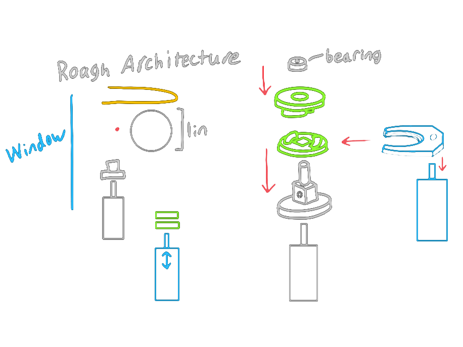
After better defining product requirements and design inputs, I started sketching concepts. This included napkin sketches, industrial design, and mechanism sketches. After some tradeoff studies, I decided on the only practical solution that meets all the requirements; a driven winch with an engagement clutch.
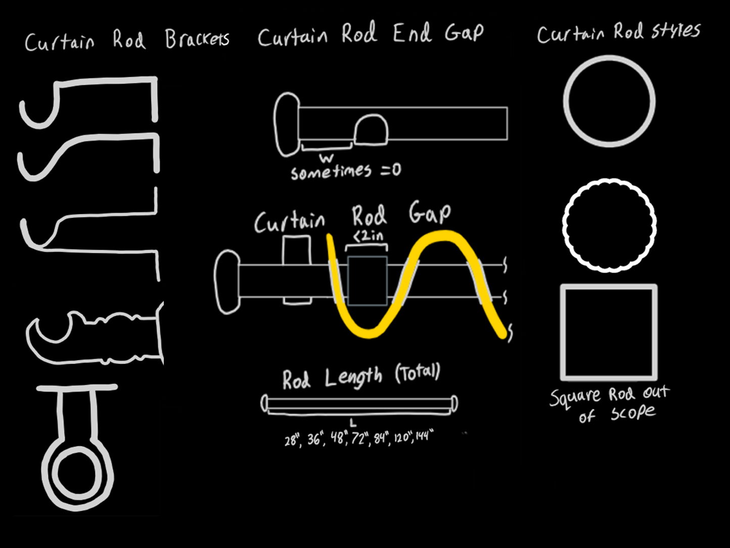
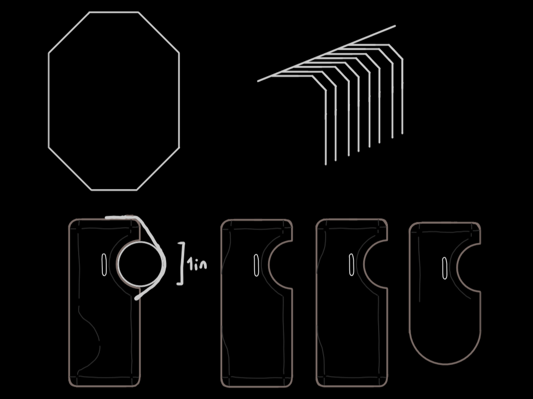
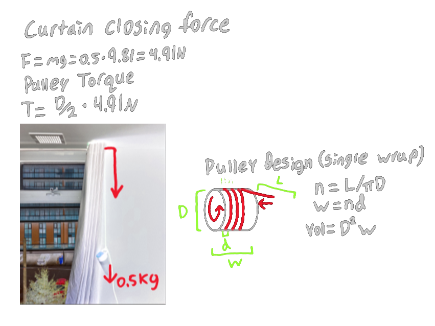
I started doing some testing to get a ballpark of how much force would be required to open my curtains. I did this by using a rope and pulley and increasing the amount of weight at the end of the rope until the curtain started moving. Using this, I could come up with a motor torque given a winch radius and gear reduction. The winch needed to have a large enough radius and length that it could hold the 60” of string, but a small enough radius such that it could have enough torque. I like to think about these decisions as design trees, where different requirements drive different parts of the design.

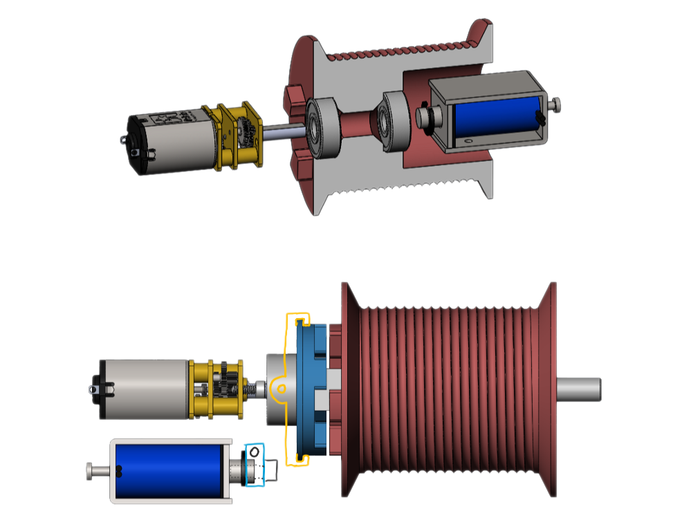
Next, I started brainstorming ways to do the clutch. Originally I wanted to do a purely mechanical design such as a centrifugal clutch - but it was far too difficult to get it to work at such low speeds. Instead I started the selection process of an actuator, including making a mock friction (only force) testing setup. I eventually settled on a micro 6V solenoid with a long stroke and low force. Another problem with the clutch approach was engaging it linearly without imposing any moment that could jam it. A picture is shown below of two concepts to apply force to the clutch (blue) without imposing a moment. A lever arm was chosen as it moves the force to the centroid of the clutch, and also can increase the force and decrease the displacement of the solenoid at the end of the lever. Another driven design diagram is shown below.

The last major design decision I will talk about is the architecture and enclosure. This is mainly driven by the size of the winch, motor, gearbox, solenoid, PCB, and clutch. It is also driven by the micro solenoid default position which in turn drives the lever - the biggest part. All of this comes together to drive the enclosure size, the shape of which is determined by the industrial design.

Design Output
Hardware
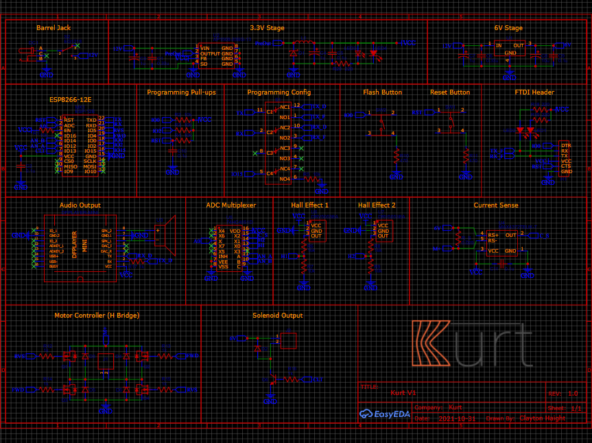
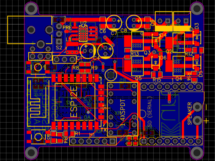
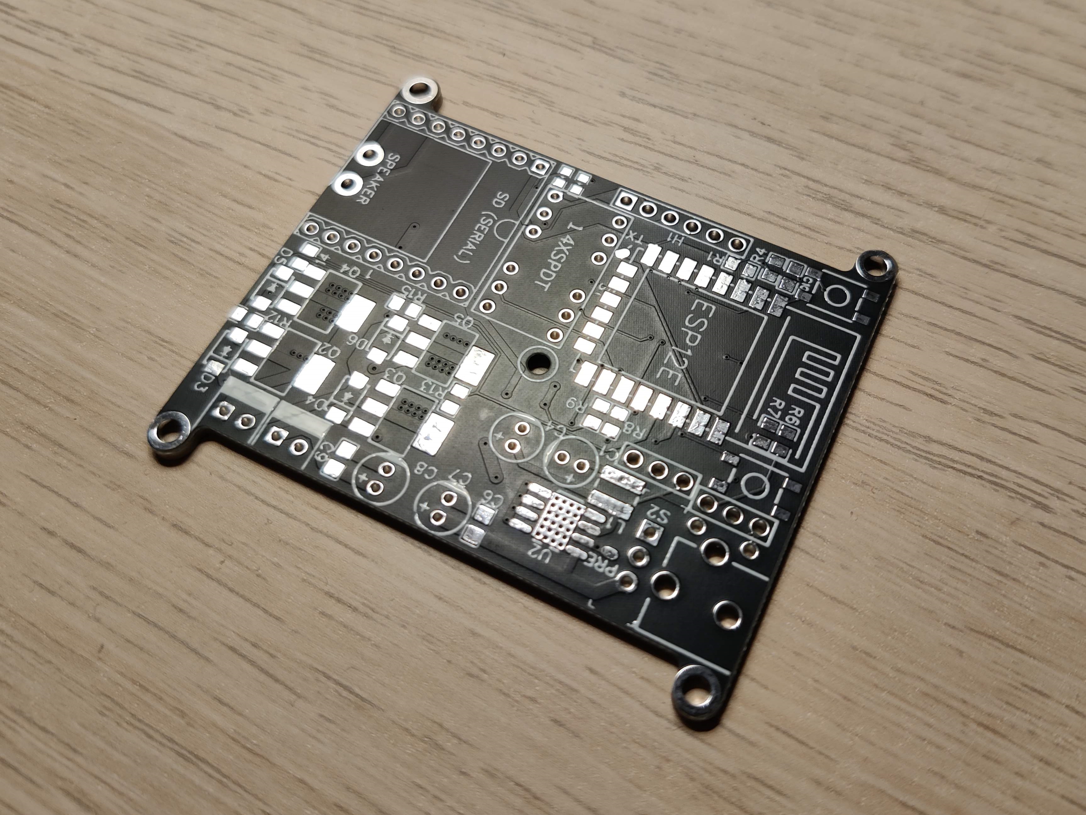
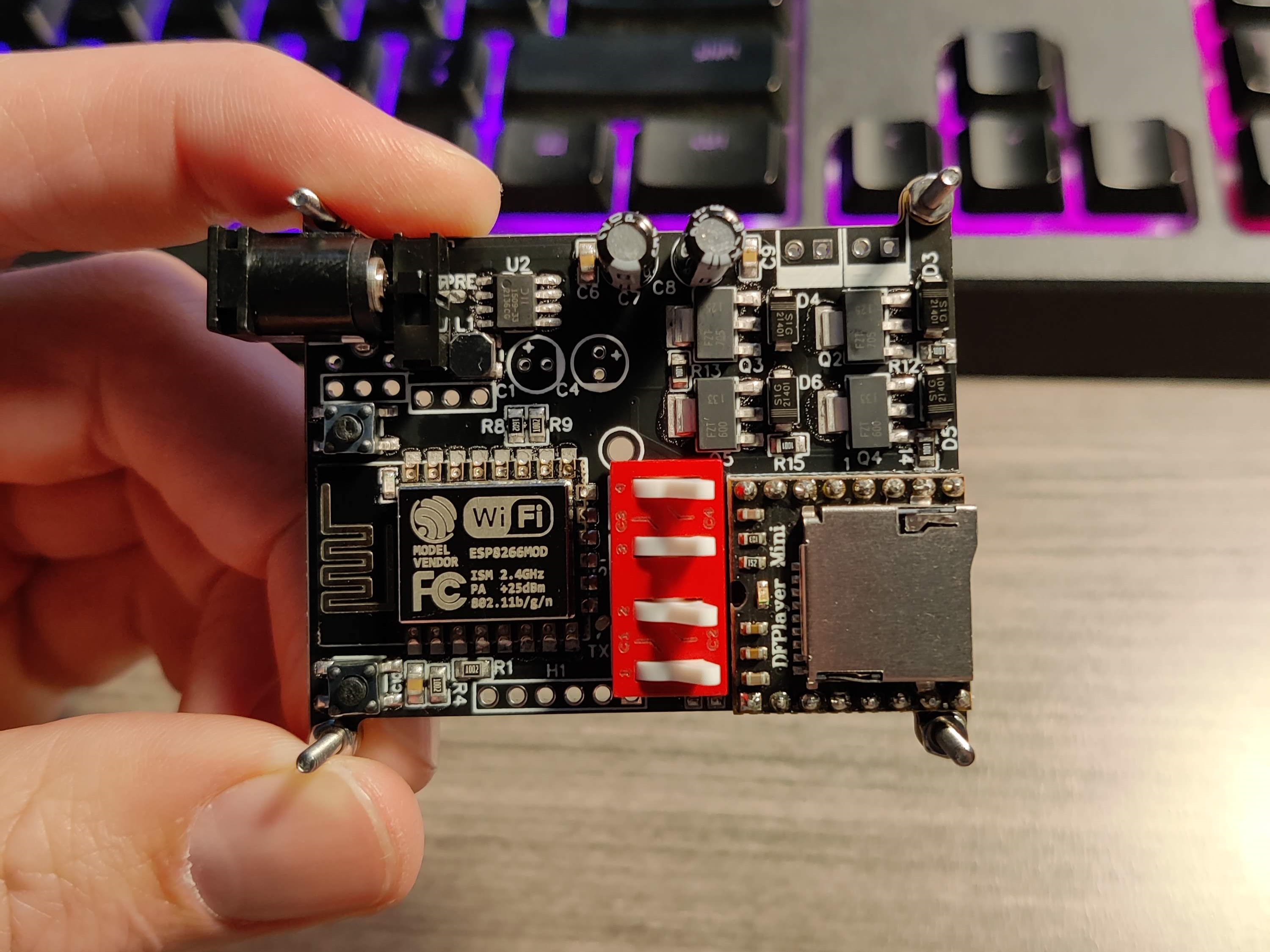
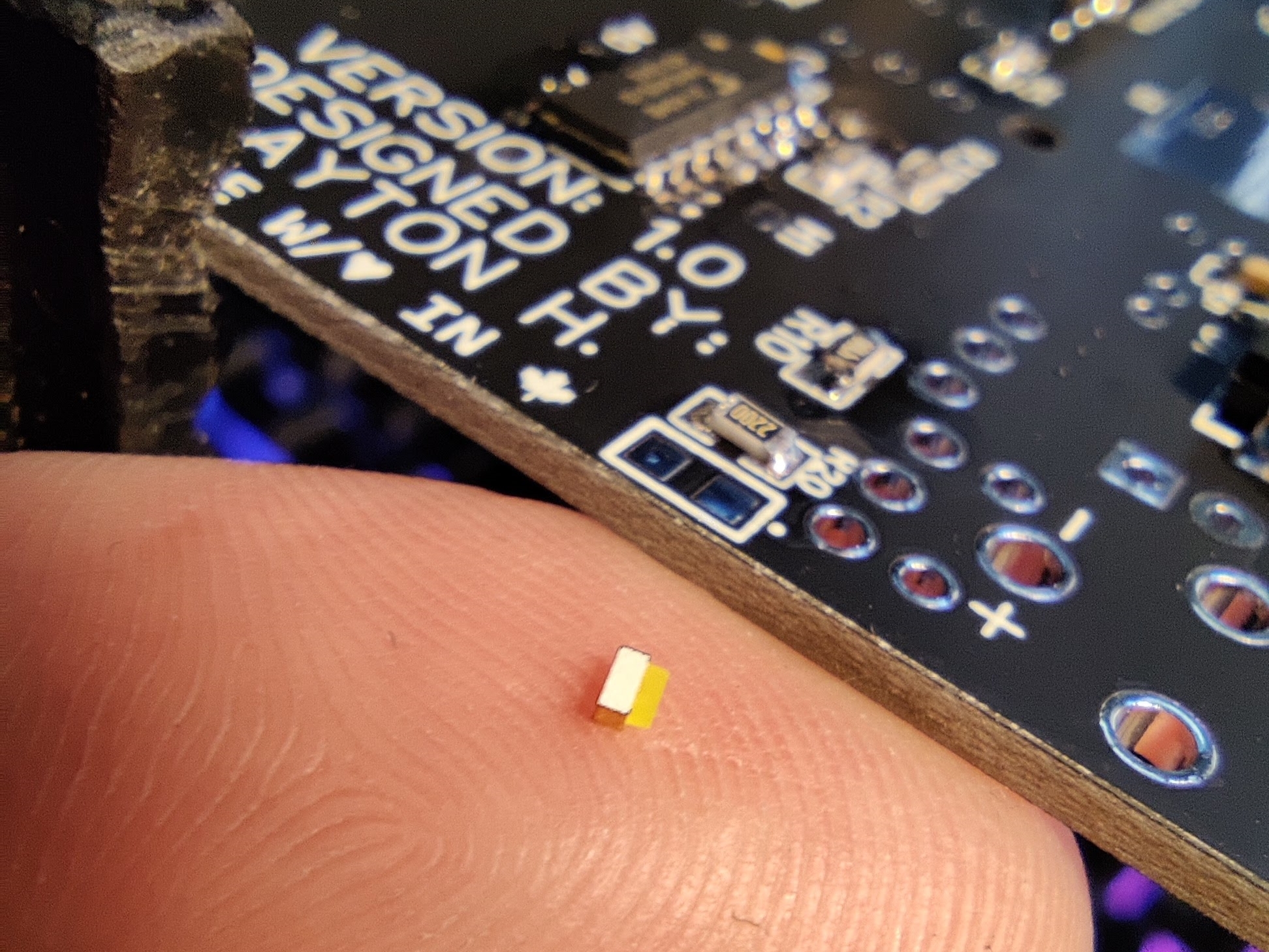
From all of the feature requirements listed above, I knew what I had to implement on the hardware side. The motor needed a motor driver, and I wasn’t happy with what was offered in hand solderable packages. To get around this I designed my own H bridge driver with MOSFETs, packaged tightly on the PCB. The solenoid needed a similar circuit which was basically a copy and paste of part of the H bridge driver. Then there was the speaker, which needed a way to play preloaded MP3 files and have an amplifier for the 1W speaker. Instead of designing a complicated circuit, I used a DFPlayer Mini which already has support for SD cards, with a built in amplifier. The brains of the operation is an ESP 12E which has a powerful microcontroller built in as well as wifi connectivity. The wifi is used for syncing an RTC and also for integration with an eventual web app. Finally the power supply system has two main levels, 3.3V and 6V. The 3.3V system uses a buck converter and is used for the microcontroller and all data connections. The 6V system uses an LDO regulator (only because I found it difficult to find an easily hand solderable buck converter that had the power requirements I needed) with big heat sink pads.
Mechanical
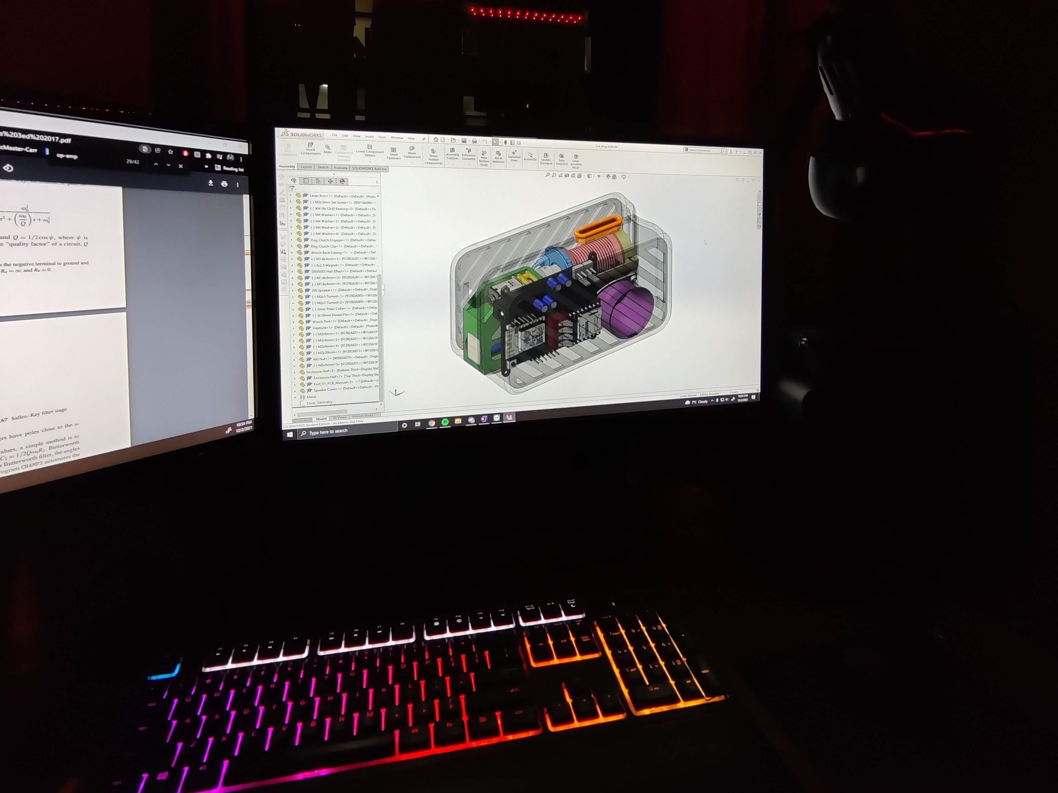
Using all the mecahnical driven design parameters from above, I mocked up the first iteration in SolidWorks. After printing off some of the parts and test fitting it into the enclosure, I wasn’t quite happy with how it looked and felt. It was too thin, long and the architecture wasn’t as dense as I wanted it to be. Because of this I wanted to go back and completely redo the architecture.
Iteration
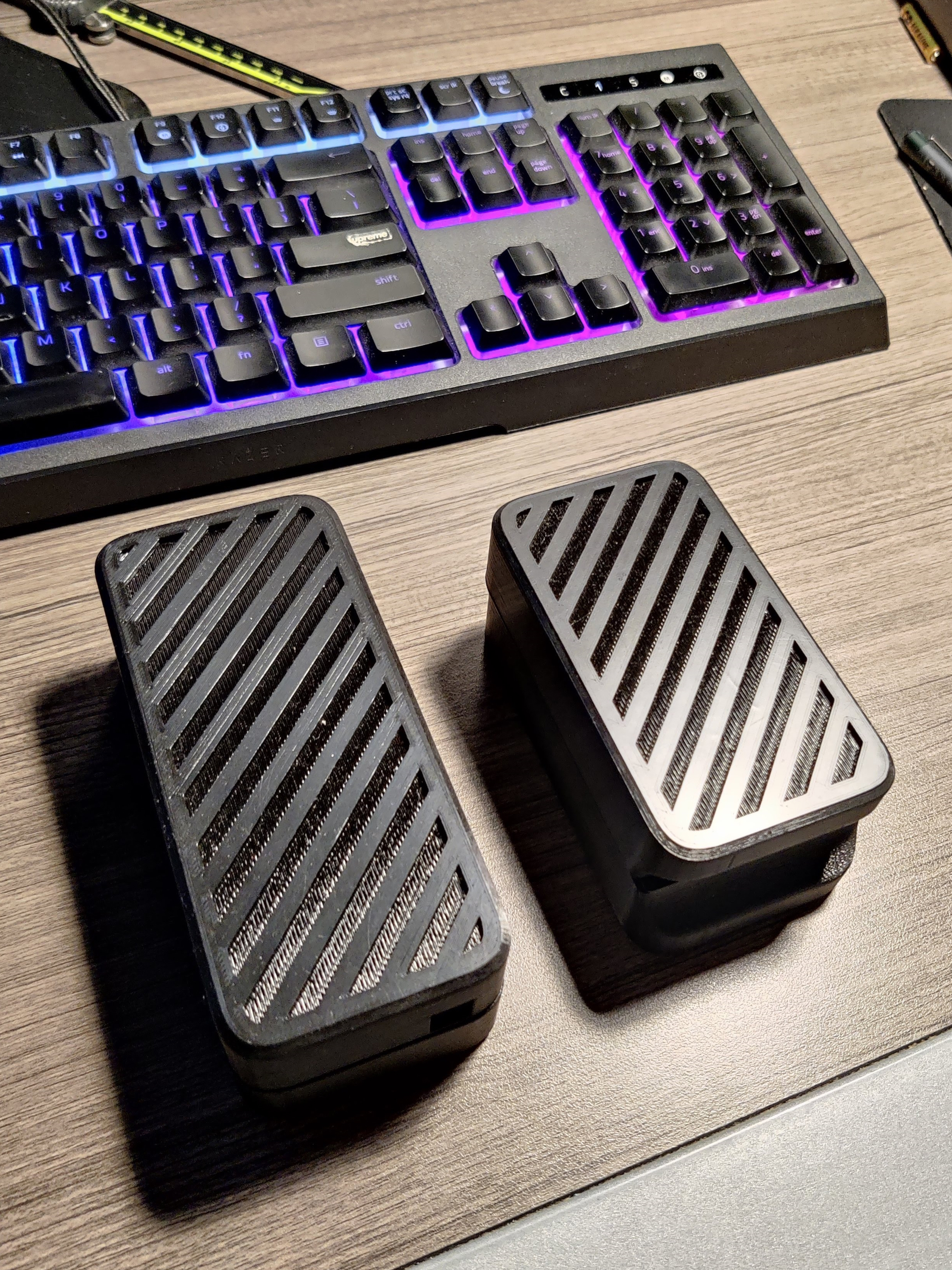
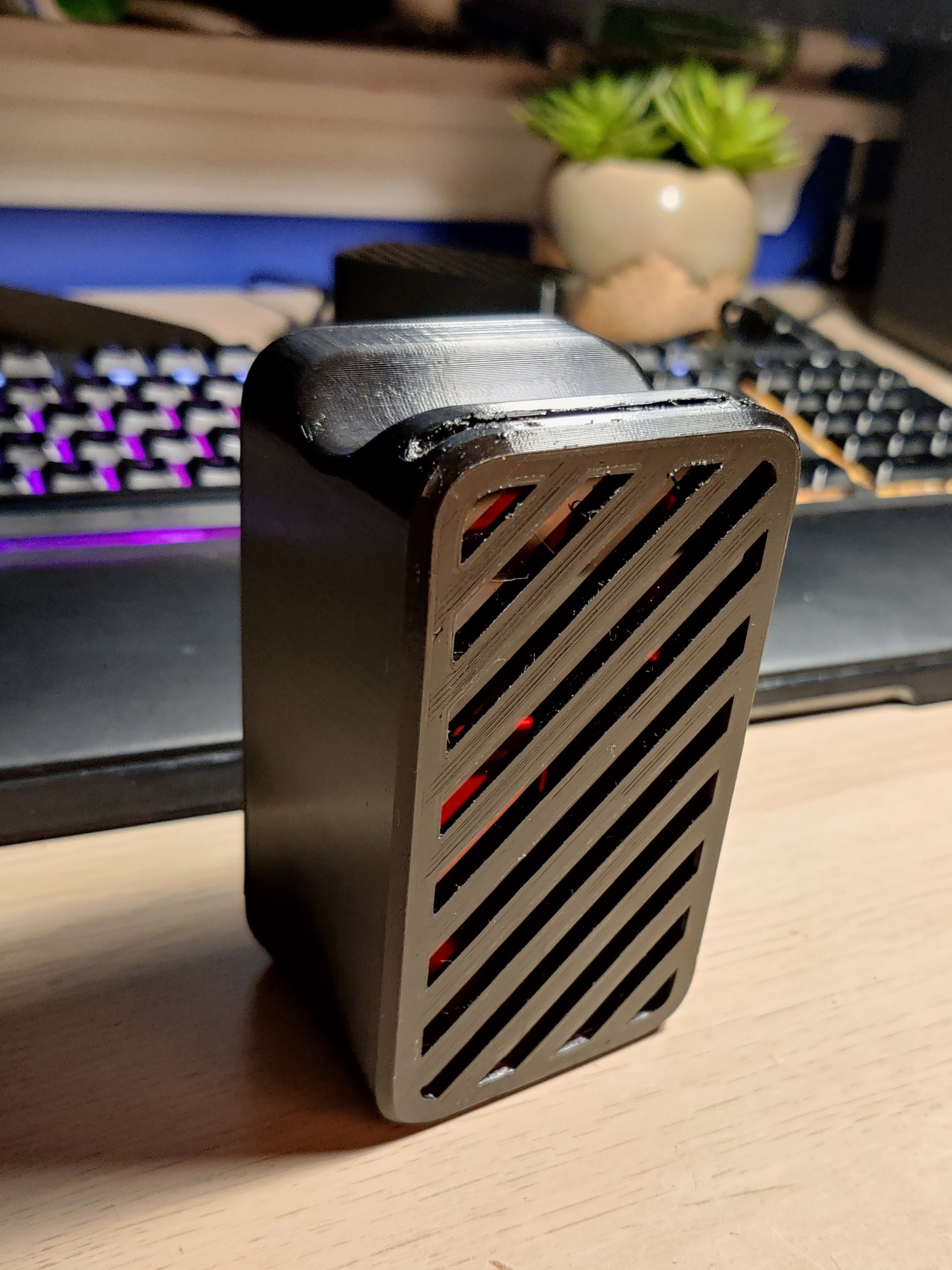
In my next iteration, I wanted to package it more tightly by optimizing for a shape where all sides are closer together (more cube-like). To do this I drew out all the possible architectures and optimized them based on minimizing empty space. The solution I came up with was stacking the PCB directly above the lever assembly. This increases the width slightly but drastically reduces the length. A picture showing a comparison between the two iterations is shown below. The image on the right is the final design.
Final Product
Kurt started as a weekend project to make a better al*rm clock and transitioned into one of my biggest projects to date. I am really proud of the outcome - it forced me to get better at PCB design, learn industrial design techniques, and ultimately go through the full product development process (excluding scaling).
This project was a really interesting and rewarding way for myself to go through the product development cycle. It's rare to find opportunities to own the entire process, and I highly recommend anyone trying to get into product design to go through the paces by yourself - it's very fulfilling. I hope Kurt proves to be useful in my everyday life and that it meets my standards of a lovable product.
